3 Soil observations and variables
Edited by: Hengl T., MacMillan R.A. and Leenaars J.G.B.
This chapter identifies and provides comprehensive definitions and descriptions for a standardized set of soil properties (and classes), which are commonly predicted using PSM. We first discuss the complexity of measuring and standardizing (or harmonizing) soil attributes, then focus on the key soil properties and classes of interest for global soil mapping. The purpose of this chapter is to serve as a reference, and background, for other chapters where the focus is on generating soil maps, interpreting accuracy results and similar.
Please note that this chapter draws extensively from materials previously published as part of the specifications for the GlobalSoilMap project (Arrouays et al. 2014). Large blocks of text extracted verbatum from these prevously published GlobalSoilMap specifications were, in fact, originally largely composed and written by the second author of this chapter in his former role as Science Coordinator for the GlobalSoilMap project (www.globalsoilmap.net). We acknowledge the source of much of the content of this chapter as having originated from the previously published GlobalSoilMap specifications.
The R tutorial at the end of the chaper reviews soil data classes and functions for R. It illustrates how to organize and reformat soil data in R for spatial analysis, how to import soil data into R and how to export data and plot it in Google Earth. To learn more about the Global Soil Information Facilities (GSIF) package, visit the main documentation page (http://gsif.r-forge.r-project.org/).
3.1 Basic concepts
3.1.1 Types of soil observations
As mentioned in the previous chapter, values for soil properties or attributes are obtained through observation and/or measurement of a soil feature, using a specified method. We refer to observations and measurements of the characteristics of soil properties and/or feature attributes as soil observations (see also the Observation and Measurements OGC standard; ISO/DIS 19156). From the perspective of the technology used, soil observations can be grouped as follows (see also Fig. 3.1):
Direct measurements obtained using analytical instruments and procedures in a laboratory or in the field — the results of measurements are analytical values considered representative for a given soil property.
Indirect soil measurements obtained using mechanical devices, analytical instruments and procedures — measurement of soil properties that can be used to infer information about a different target soil property. These can be based on soil spectroscopy and similar close-range or remote sensing systems (Shepherd and Walsh 2007; Viscarra Rossel, McBratney, and Minasny 2010).
Direct observations of soil properties and interpretations — subjectively assessed values based on protocols for soil description as presented in manuals i.e. abundance of mottles, soil drainage class, soil colour.
Indirect or derived interpretations — subjectively assessed values or conditions based mainly on an expert’s knowledge and interpretation of observations e.g. soil classification, soil fertility class.
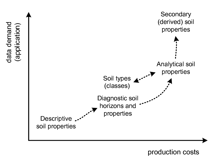
Figure 3.1: Types of soil observations in relation to data usage and production costs. Descriptive soil observations (e.g. manual texture or diagnostic soil horizons) are often not directly useable by end users, who are often more interested in specific secondary soil properties (e.g. water holding capacity, erosion index, soil fertility) as inputs to their modeling. However, descriptive field observations are often orders of magnitude more affordable to obtain than laboratory analysis.
Field campaigns are usually the most costly part of soil surveys. Large numbers of soil observations are made in the field to assess the spatial distribution of readily observable soil properties to provide empirical evidence for soil mapping. Because a soil analytical measurement in the laboratory is generally much more costly than a soil observation in the field, only a smaller subset of soil samples is taken from the larger number of field soil observations and brought to the laboratory for subsequent analysis. Ideally, every soil observation would be accompanied by corresponding soil analytical measurements to produce the most accurate and comprehensive soil information possible.
It is important to emphasize that soil properties, and the methods used to assess soil properties, are two distinctly different concepts. The two can be defined together (functional definition) or can be defined separately, as given by numerous national and international manuals and guidelines for analytical procedures and soil description: e.g. in Natural Resources Conservation Service (2004; Carter and Gregorich 2007; Food and United Nations 2006), and/or Van Reeuwijk (2002). In this chapter we also make a distinction between the ‘targeted variable’ (targeted soil properties) and ‘paths’ (determination methods).
Soil analytical data obtained in a laboratory are typically an order of magnitude more expensive to produce than descriptive field observations (Burrough, Beckett, and Jarvis 1971; Gehl and Rice 2007; B. Kempen 2011). To reduce these high costs, surveyors collect descriptive soil observations (Fig. 3.1), which can subsequently be interpreted and linked to soil types and soil classes, which are then assumed to be characterised by a limited and definable range of soil properties (Bouma, Batjes, and Groot 1998). It is also possible to convert observed values for certain soil properties to values comparable to those measured by analytical methods (albeit with unknown precision) by using various calibration models or conversion functions. For example, manual texturing analysis (FAO 1990; Soil survey Division staff 1993) can be used as a basis for estimating soil texture fractions with a precision of ±5 % at fraction of the cost of laboratory analysis.
Soils are usually sampled per depth interval or layer, generally using a genetic A-B-C-R system i.e. corresponding to a soil horizon — a relatively homogeneous layer of soil (with upper and lower depth) that is “distinctly different from other layers and informative for the soil’s nature” (Harpstead, Sauer, and Bennett 2001). Actual soil samples are either taken from the centre of a soil horizon or are mixed samples of the material from the whole horizon (Fig. 3.2). Decades of soil survey have shown that soil horizons can be fuzzy objects. They may be difficult for different surveyors to distinguish and delineate consistently (Burrough 1989; de Gruijter, Walvoort, and Gaans 1997). Soil correlation exercises try (not always successfully) to help different surveyors consistently recognize similar soil horizons and assign similar codes with comparable upper and lower boundaries so as to produce similar descriptions and classifications for any observed soil.
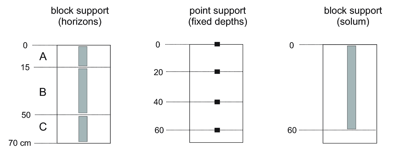
Figure 3.2: Soil observations can refer to genetic horizons (left), fixed depths i.e. point support (center) and/or can refer to aggregate values for the complete profile (right).
An emerging approach to soil characterization is to scan the complete soil profile in different parts of the spectra, and then decide on vertical stratification a posteriori (Viscarra Rossel, McBratney, and Minasny 2010). Nevertheless, much of the analytical data available in existing legacy soil profile databases is sampled per soil layer and described by soil horizon.
Soil observations are taken at a geographic position and at a specific depth (or depth interval), which is either 3D or refers to the whole solum. The 3D (longitude, latitude, depth) position implies that the property varies not only in geographic space, but also with depth. Soil properties that describe an entire site are by implication 2D, as are soil properties that summarise or refer to the soil profile as a whole entity. For example, soil type does not change with depth. Also rock outcrops, depth to bedrock and depth to ground water table are single attributes that apply to an entire profile.
3.1.2 Soil properties of interest for global soil mapping
There are many soil properties, possibly hundreds, used in the international domain of soil science including pedology, soil survey, soil fertility, soil hydrology, soil biology, etc. Not all of these can be mapped globally, nor are all of explicit interest for global applications or use.
Soil data have been, and are, collected and compiled into maps at various scales for various purposes and soil inventory projects typically begin by first carefully identifying the specific list of soil properties that are of most interest for the anticipated uses of the planned survey. Different soil data are required for different purposes, such as applying different models with different data requirements.
In the past, soil surveys typically elected to focus on observing and measuring soil attributes and properties that were considered to be relatively stable, or static, in time. For example the particle size distribution of a soil, or its depth to bedrock, were considered to be relatively stable and not subject to large changes over relatively short time periods (e.g. decades). Even attributes that were known to change with management and time, such as topsoil thickness, organic carbon or pH, were treated as relatively stable properties for the purposes of mapping.
This choice to emphasize relatively stable soil properties and attributes was a logical consequence of the fact that it could take years to produce a single soil map and decades to complete mapping for an entire area of interest. Consequently, for maps to be relevant, and to remain relevant and useful for their anticipated lifetime of use, they had to restrict themselves to trying to describe the variation in only space (not time) of properties that could be considered stable and static.
The idea that soil properties could be assumed to remain relatively stable through time was partially based on an assumption that most soils had achieved a relatively stable condition that was in equilibrium with their current environment. If a soil is in equilibrium with its environment, it can be assumed that it will retain its present attributes, since there are no strong drivers for change. This may well apply to undisturbed soils in their natural environment, but it is not valid for disturbed or managed soils. It is well established that human management practices can, and do, significantly alter some key soil properties, such as pH, organic matter and topsoil thickness. Most conventional soil maps recognized, and reported on, differences in soil properties, such as pH or organic matter, between natural soils and managed soils. However, it was never a common practice to name, map and characterize managed soils separately from natural soils.
Local or national soil survey projects are of direct relevance to global soil mapping initiatives if the range of data collected encompasses the minimum data set as specified for global initiatives. For example, completion of an update to the SOTER database for the World requires an extensive range of soil property data as specified in the procedures manual (Van Engelen and Dijkshoorn 2012). An update of the Harmonised World Soil Database (FAO/IIASA/ISRIC/ISS-CAS/JRC 2012) requires a smaller range of attributes. The GlobalSoilMap project (D. Arrouays et al. 2014) selected a list of only 12 soil properties considered relevant for global analyses, and feasible to map globally. This list includes seven basic attributes, assessed through primary observation or measurement, and three derived attributes which are calculated from the primary soil properties (Tbl. 3.1). These attributes are being mapped (where possible) at a fine resolution of six depth intervals in the vertical and, 3–arcseconds in the horizontal dimension (ca. 100 m) (Fig. 3.3).
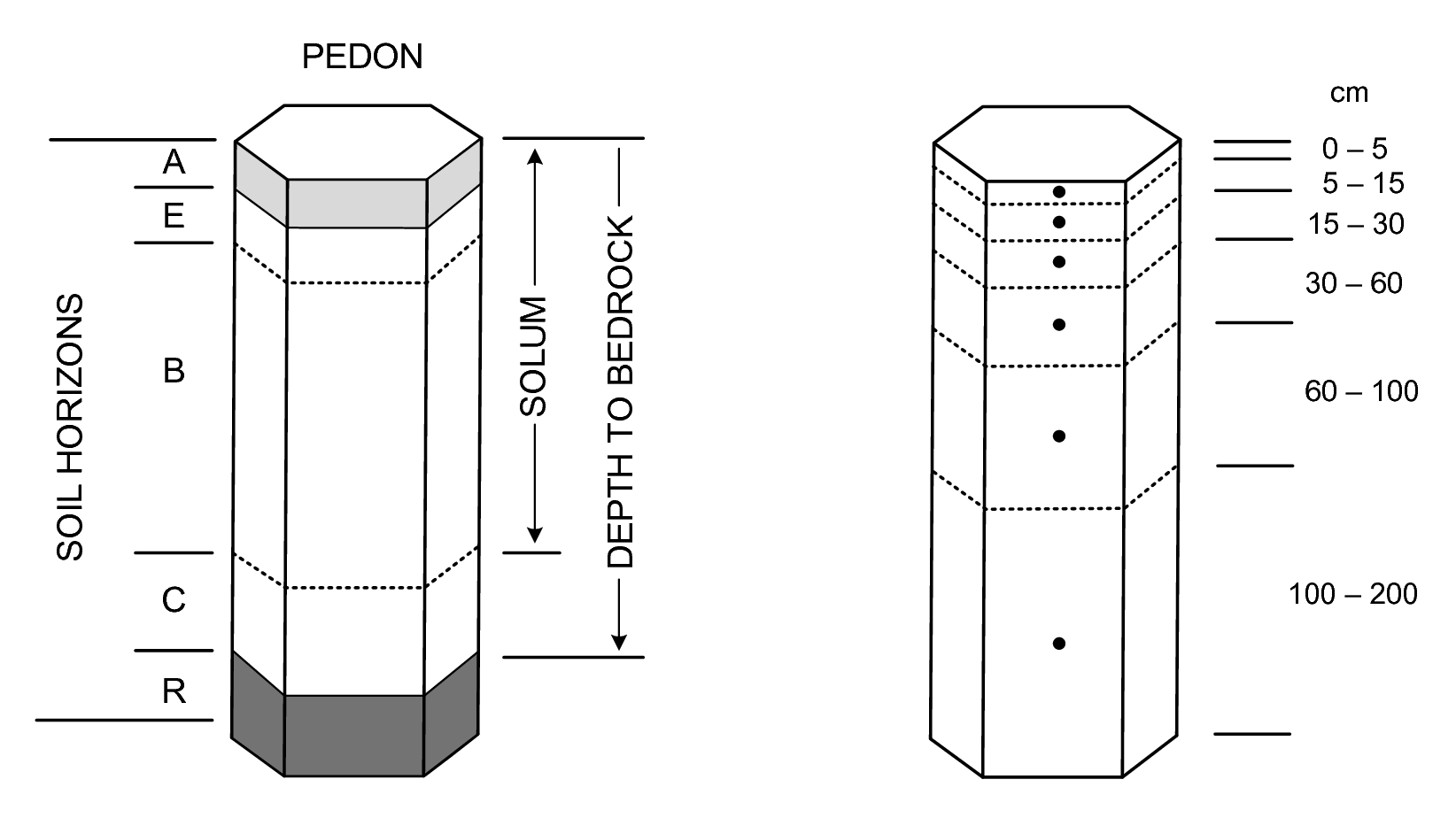
Figure 3.3: Standard soil horizons, solum thickness and depth to bedrock (left) vs six standard depths used in the GlobalSoilMap project (right).
| Variable | Units | Reference |
|---|---|---|
| Total profile depth (depth to bedrock) | cm | (SSDS, 1993; p.5) |
| Plant exploitable (effective depth) | cm | (SSDS, 1993; p.60) |
| Soil organic carbon (dry combustion) | permille | ISO 10694 |
| pH index (the 1:5 H2O solution) | – | ISO 10390 |
| Sand content (gravimetric) | % | (NRCS, 2004; p.347) |
| Silt content (gravimetric) | % | (NRCS, 2004; p.347) |
| Clay content (gravimetric) | % | (NRCS, 2004; p.347) |
| Coarse fragments (volumetric) | % | (NRCS, 2004; p.36) |
| Effective Cation Exchange Capacity | cmol | ISO 11260 |
| Bulk density of the whole soil | kg/cubic-m | ISO 11272 |
3.1.3 Reference methods
A pragmatic solution to ensuring efficient exchange, sharing and interpretation of global soil data is to establish reference methods for soil measurement and description. The GlobalSoilMap project agreed that their target soil properties would be assessed and reported relative to specific, designated reference methods. For example, soil organic carbon content of the fine earth fraction is to be assessed and reported according to ISO10694 dry combustion method (Sleutel et al. 2007). Values for pH are to be be reported for a 1:5 suspension of soil in water or using the CaCl\(_2\) solution, with a precision of 1 decimal place. It has also been recommended that ISO TC 190 — soil quality standards — should be used to assess and report all data measured from air-dried soil samples.
Soil properties designated as optional for the GlobalSoilMap consortium include Effective Cation Exchange Capacity assessed and reported according to ISO11260 Barium Chloride (cmol+/kg = centi-mole+ per kilogram) and Electrical conductivity in 1:1 soil–water solution (dS/m = deci-siemens per metre). The list of soil properties identified for routine global soil mapping and modelling is likely to grow in the years to come.
ISO TC-190 and
ISO TC-345. Such unambiguously defined international standards are
crucial for success of the multi-partner global soil mapping projects.
In the following sections we focus our discussion on the soil properties
that were first mapped for the https://soilgrids.org project:
depth to bedrock, occurrence of the R horizon, organic carbon content of the fine earth
fraction, pH of the fine earth fraction, particle size class contents
(sand, silt, clay) of the fine earth fraction, gravel content of the
whole soil, bulk density of the whole soil (and subsequently of the fine
earth fraction) and Cation Exchange Capacity of the fine earth fraction.
We define those attributes as completely and unambiguously as possible,
including the associated reference method. For each soil property the
following will be discussed:
Brief introduction to the soil property (what is it, what does it reflect, why is it of interest, considerations; in general terms);
Definition of the soil feature related to the soil property and its spatial domain (2D, 3D);
Definition of the reference methods used to assess the soil property value;
Definition of the convention used to express the soil property value (units, precision, range);
Review of the variation in soil property definitions and in methods to assess the attribute, including listings of several of the most widely used conversion functions cited from literature, and with emphasis on harmonization or conversion to the reference method.
We also identify, and review, a number of other widely used measurement methods, in addition to our selected standard methods. We describe if and how these other methods relate to the selected reference methods and discuss issues related to harmonization and standardization for attributes of current interest for global mapping.
3.1.4 Standard soil variables of interest for soil mapping
Some standard soil legends for listed soil properties are embedded within the GSIF package and can be loaded by:
library(GSIF)
#> GSIF version 0.5-5 (2019-01-04)
#> URL: http://gsif.r-forge.r-project.org/
data(soil.legends)
str(soil.legends)
#> List of 12
#>  $ ORCDRC  :'data.frame':    40 obs. of  4 variables:
#>   ..$ MIN  : num [1:40] 0 0.2 0.4 0.6 0.8 1.1 1.5 1.9 2.4 3 ...
#>   ..$ MAX  : num [1:40] 0.2 0.4 0.6 0.8 1.1 1.5 1.9 2.4 3 3.6 ...
#>   ..$ CPROB: num [1:40] 0.0161 0.0301 0.0518 0.0717 0.113 0.159 0.203 0.264 0.328 0.373 ...
#>   ..$ COLOR: chr [1:40] "#000180" "#000393" "#0006A6" "#000FB7" ...
#>  $ PHIHOX  :'data.frame':    40 obs. of  4 variables:
#>   ..$ MIN  : num [1:40] 20 42 45 46 48 49 50 51 52 53 ...
#>   ..$ MAX  : num [1:40] 42 45 46 48 49 50 51 52 53 54 ...
#>   ..$ CPROB: num [1:40] 0.0125 0.0375 0.0625 0.0875 0.1125 ...
#>   ..$ COLOR: chr [1:40] "#FF0000" "#FF1C00" "#FF3900" "#FF5500" ...
#>  $ PHIKCL  :'data.frame':    40 obs. of  4 variables:
#>   ..$ MIN  : num [1:40] 20 33 35 36 37 38 38.5 39 40 40.5 ...
#>   ..$ MAX  : num [1:40] 33 35 36 37 38 38.5 39 40 40.5 41 ...
#>   ..$ CPROB: num [1:40] 0.0125 0.0375 0.0625 0.0875 0.1125 ...
#>   ..$ COLOR: chr [1:40] "#FF0000" "#FF1C00" "#FF3900" "#FF5500" ...
#>  $ BLDFIE  :'data.frame':    40 obs. of  4 variables:
#>   ..$ MIN  : num [1:40] 200 850 1000 1100 1150 1200 1220 1260 1300 1310 ...
#>   ..$ MAX  : num [1:40] 850 1000 1100 1150 1200 1220 1260 1300 1310 1340 ...
#>   ..$ CPROB: num [1:40] 0.0125 0.0375 0.0625 0.0875 0.1125 ...
#>   ..$ COLOR: chr [1:40] "#3D3FFF" "#3A42FF" "#3745FF" "#304CFF" ...
#>  $ CECSOL  :'data.frame':    40 obs. of  4 variables:
#>   ..$ MIN  : num [1:40] 0 5 5.2 5.3 5.5 5.8 6 6.3 6.7 7.1 ...
#>   ..$ MAX  : num [1:40] 5 5.2 5.3 5.5 5.8 6 6.3 6.7 7.1 7.5 ...
#>   ..$ CPROB: num [1:40] 0.23 0.241 0.247 0.259 0.277 0.292 0.308 0.328 0.351 0.37 ...
#>   ..$ COLOR: chr [1:40] "#001998" "#0025A4" "#0031B1" "#003EBD" ...
#>  $ SNDPPT  :'data.frame':    40 obs. of  4 variables:
#>   ..$ MIN  : num [1:40] 0 1 3 4 6 8 10 12 14 16 ...
#>   ..$ MAX  : num [1:40] 1 3 4 6 8 10 12 14 16 19 ...
#>   ..$ CPROB: num [1:40] 0.0125 0.0375 0.0625 0.0875 0.1125 ...
#>   ..$ COLOR: chr [1:40] "#FFFF00" "#F8F806" "#F1F10C" "#EBEB13" ...
#>  $ SLTPPT  :'data.frame':    40 obs. of  4 variables:
#>   ..$ MIN  : num [1:40] 0 2 3 4 5 6.7 8 9 10 12 ...
#>   ..$ MAX  : num [1:40] 2 3 4 5 6.7 8 9 10 12 13 ...
#>   ..$ CPROB: num [1:40] 0.0125 0.0375 0.0625 0.0875 0.1125 ...
#>   ..$ COLOR: chr [1:40] "#FFFF00" "#F8F806" "#F1F10C" "#EBEB13" ...
#>  $ CLYPPT  :'data.frame':    40 obs. of  4 variables:
#>   ..$ MIN  : num [1:40] 0 2 3 4 5 6 7 8 9.3 10 ...
#>   ..$ MAX  : num [1:40] 2 3 4 5 6 7 8 9.3 10 12 ...
#>   ..$ CPROB: num [1:40] 0.0125 0.0375 0.0625 0.0875 0.1125 ...
#>   ..$ COLOR: chr [1:40] "#FFFF00" "#F8F806" "#F1F10C" "#EBEB13" ...
#>  $ CRFVOL  :'data.frame':    40 obs. of  4 variables:
#>   ..$ MIN  : num [1:40] 0 0.1 0.3 0.4 0.6 0.8 1 1.2 1.5 1.8 ...
#>   ..$ MAX  : num [1:40] 0.1 0.3 0.4 0.6 0.8 1 1.2 1.5 1.8 2.2 ...
#>   ..$ CPROB: num [1:40] 0.408 0.41 0.411 0.416 0.418 0.504 0.506 0.513 0.514 0.558 ...
#>   ..$ COLOR: chr [1:40] "#FFFF00" "#FDF800" "#FBF100" "#F9EB00" ...
#>  $ TAXOUSDA:'data.frame':    74 obs. of  4 variables:
#>   ..$ Number : int [1:74] 0 1 2 3 5 6 7 10 11 12 ...
#>   ..$ Group  : Factor w/ 75 levels "","Albolls","Anthrepts",..: 39 50 47 38 35 54 41 28 26 34 ...
#>   ..$ Generic: Factor w/ 17 levels "","Alfisols",..: 11 14 13 8 6 6 6 7 7 7 ...
#>   ..$ COLOR  : chr [1:74] "#1414FF" "#D2D2D2" "#FFB9B9" "#F5F5F5" ...
#>  $ TAXGWRB :'data.frame':    32 obs. of  4 variables:
#>   ..$ Number: int [1:32] 1 2 3 4 5 6 7 8 9 10 ...
#>   ..$ Code  : Factor w/ 32 levels "AB","AC","AL",..: 2 1 3 4 6 5 8 9 7 10 ...
#>   ..$ Group : Factor w/ 32 levels "Acrisols","Albeluvisols",..: 1 2 3 4 5 6 7 8 9 10 ...
#>   ..$ COLOR : chr [1:32] "#FDA463" "#FFEBBE" "#FFFFCC" "#FC6B5D" ...
#>  $ TAXNWRB :'data.frame':    118 obs. of  5 variables:
#>   ..$ Number        : int [1:118] 1 2 3 4 5 6 7 8 9 10 ...
#>   ..$ Group         : Factor w/ 118 levels "Acric Ferralsols",..: 28 29 30 31 104 116 32 84 111 18 ...
#>   ..$ Shortened_name: Factor w/ 118 levels "Acric.Ferralsols",..: 28 29 30 31 104 116 32 84 111 18 ...
#>   ..$ Generic       : Factor w/ 30 levels "Acrisols","Albeluvisols",..: 1 1 1 1 1 1 2 2 2 3 ...
#>   ..$ COLOR         : chr [1:118] "#FE813E" "#FD9F39" "#FDAE6B" "#FD8D3C" ...
which illustrates the referent cumulative probabilities (CPROB) and
appropriate color legend (COLOR; coded as a six-digit, three-byte
hexadecimal number) for the values of the target soil variables. The cumulative
probabilities were derived using the collection of records in the WoSIS
repository (Batjes et al. 2017), and can be considered as an estimate of global prior
probabilities for soil pH (see further Fig. 3.7).
A general intention is to maintain a Global Soil Data Registry so that a short variable name (in further text “variable code”) can be linked to a unique set of metadata which should include:
Full description (text);
Variable type (numeric, quantity, binary, factor etc);
Determination / measurement method (unique code);
Measurement unit (following the International System of Units);
Biblio reference (URL or DOI);
ISO code (if available);
Physical limits (lower / upper);
Detection limit (i.e. numeric resolution);
Priority level (required, suggested or optional);
Note that MySQL has some restrictions considering column names: special characters, such as those outside the set of alphanumeric characters from the current character set, can not be used in the column names. Proposed abbreviations for standard method names are \(\mathtt{VOL}\) — volume fraction, \(\mathtt{ABU}\) — abundance or relative area cover, \(\mathtt{PCT}\) — mass percentage, \(\mathtt{ICM}\) — thickness in cm, \(\mathtt{MHT}\) — texture by-hand or manual hand texture and \(\mathtt{MNS}\) — Munsell color codes, horizon sequence is coded with the capital ASCII letters e.g. \(\mathtt{A}\), \(\mathtt{B}\), \(\mathtt{C}\),\(\ldots\) \(\mathtt{Z}\). Another option is to simply use the US Goverment National Cooperative Soil Characterization Database column names (http://ncsslabdatamart.sc.egov.usda.gov/).
Also note that the metadata can be easily separated from the code so that the short codes (variable name) can be used as a shorthand (replacement) for the long description of the complete metadata. Using short codes is also important for programming because unique code names are used consistently in all scripts / functions.
3.2 Descriptive soil profile observations
3.2.1 Depth to bedrock
Soil depth (specifically depth to bedrock) is predicted because it is an important consideration for a wide variety of engineering, hydrological and agronomic interpretations. Shallow and lithic soils are of particular interest as they impose restrictions for foundations and structures in engineering, limit infiltration and storage of moisture and produce more rapid runoff and erosion and limit growth of many crops by restricting rooting depth and limiting available moisture storage. Most soil legacy profile data do not provide any information about the soil below depths of 1 m (Richter and Markewitz 1995). This characteristic of legacy soil data limits its usefulness for predicting soil depths greater than 2 m.
Soil depth is measured from the soil surface downwards and expressed in
positive values increasing with depth. Google Earth and the KML data
standard (via the altitudeMode tag) allow one to specify if the
vertical dimension refers to actual altitude (vertical distance from the
land surface) or to distance from the sea level (absolute). In this
case soil depths can be represented using clampToGround and negative
values. For example, a depth of 30 cm can be expressed as (Wilson 2008):
<Placemark> <Point>
<altitudeMode>clampToGround</altitudeMode>
<coordinates>17.2057,45.8851,-0.3</coordinates>
</Point> </Placemark>
Soil surface (depth = 0 cm) is the top of the mineral soil; or, for soils
with a litter layer (O horizon), the soil surface is the top of the
part of the O horizon that is at least slightly decomposed (FAO 2006).
Fresh leaf or needle fall that has not undergone observable
decomposition is not considered to be part of the soil and may be
described separately. For organic soils, the top of any surface horizon
identified as an O horizon is considered the soil surface.
The depth to bedrock i.e. depth to the R horizon is measured from
the soil surface downwards and is expressed in cm with a precision of ±1 cm.
Depth to bedrock deeper than e.g. 2–3 m is most often not recorded. Bedrock
is consolidated hard rock, with only a few cracks, underlying the soil. It
is not necessarily parent material. We imagine it often as something
distinct and easy to recognize in the field. In practice, depth to
bedrock can be difficult to determine, and is often confused with
stoniness or depth to parent material (which can be unconsolidated
material). Another issue is that, for most of the soils in the world,
hard bedrock is >2 m deep so that we actually don’t know the correct
depth to enter, other than >2 m. Rootability is physically restricted by
the bedrock, whether hard or soft (see Fig. 3.4).
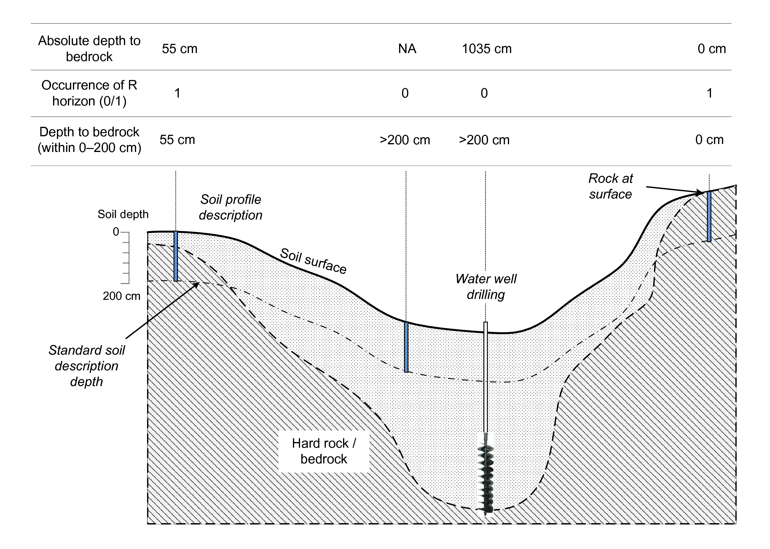
Figure 3.4: Depth to bedrock for censored and uncensored observations. Image source: Shangguan et al. (2017) doi: 10.1002/2016MS000686.
In traditional soil characterisation, the total depth of the O,
A, E, and B horizons is referred to as the solum
(Harpstead, Sauer, and Bennett 2001), while the underlaying layer is referred to as
parent material or substratum (Soil survey Division staff 1993). Parent material can be coarse
or fine unconsolidated deposits of e.g. alluvial, colluvial or windblown
origin (C horizon) or consolidated residual hard bedrock (R
horizon).
R horizon (layer
impenetrable by roots or agricultural machinery). Depth to bedrock deeper
than 2 m is most often not recorded in field survey descriptions.
3.2.2 Effective soil depth and rooting depth
Effective soil depth is of interest for soil mapping because it is a key indicator of the capability of the soil to store moisture, support crop growth and sustain beneficial land uses. It is often an essential indicator of soil health. The effective soil depth is the depth to which micro-organisms are active in the soil, where roots can develop and where soil moisture can be stored (FAO 2006).
| Biome | N | MMRD | HVRD |
|---|---|---|---|
| Boreal Forest | 6 | 2.0 ± 0.3 | 3.3 |
| Cropland | 17 | 2.1 ± 0.2 | 3.7 |
| Desert | 22 | 9.5 ± 2.4 | 53.0 |
| Sclerophyllous shrubland and forest | 57 | 5.2 ± 0.8 | 40.0 |
| Temperate coniferous forest | 17 | 3.9 ± 0.4 | 7.5 |
| Temperate deciduous forest | 19 | 2.9 ± 0.2 | 4.4 |
| Temperate grassland | 82 | 2.6 ± 0.2 | 6.3 |
| Tropical deciduous forest | 5 | 3.7 ± 0.5 | 4.7 |
| Tropical evergreen forest | 5 | 7.3 ± 2.8 | 18.0 |
| Tropical savanna | 15 | 15.0 ± 5.4 | 68.0 |
There are many thoughts on how to define effective soil depth. Effective soil depth is closely related to, but not necessarily equivalent to, the rooting depth. Rooting depth is measured and reported relative to a specific prevailing land cover and land use category, while effective soil depth is supposedly the maximum possible depth of soil that can be used by any growing plant (see Tbl. 3.2).
In some cases soil ends with an abrupt change of material which is either solid, compacted or distinctly impenetrable for plants and organisms living in soil. The root restricting i.e. plant accessible depth, is the depth at which root penetration is strongly inhibited because of physical (including soil temperature), chemical or hydrological characteristics (Soil survey Division staff 1993, Handbook 18:60). Restriction means the inability to support more than a very few fine (or few very fine roots) if depth from the soil surface and water state, other than the occurrence of frozen water, are not limiting. For some crops like cotton plants or soybeans, and possibly other crops with less abundant roots than the grasses, the “very few” class is used instead of the “few” class. The restriction may be below where plant roots normally occur because of limitations in water state, temperatures, or depth from the surface. This evaluation can be based on the specific plants that are important to the use of the soil, as indicated in Tbl. 3.2; see also Soil survey Division staff (1993, Handbook 18:60).
Root restriction can be also influenced by certain pedogenic horizons, such as fragipans. A change in particle size distribution alone, as for example loamy sand over gravel, is not always a basis for physical root restriction. A common indication of physical root restriction is a combination of structure and consistence which together suggest that the resistance of the soil fabric to root entry is high and that vertical cracks and planes of weakness for root entry are absent or widely spaced. Root restriction is inferred for a continuously cemented zone of any thickness; or a zone >10 cm thick that when very moist or wet is massive, platy, or has weak structure of any type for a vertical repeat distance of >10 cm and while very moist or wet is very firm (firm, if sandy), extremely firm, or has a large penetration resistance. Chemical restrictions, such as high extractable aluminium, manganese and/or low extractable calcium, can also be considered but are plant-specific. Root-depth observations preferably should be used to make the generalization. If these are not available then inferences may be made from soil morphology.
As a general recommendation, it is advisable to focus first on mapping soil properties that limit rooting, including content of coarse fragments and the depth to bedrock, and then define effective soil depth a posteriori using distinct analytical rules. A similar approach has also been promoted by Rijsberman and Wolman (1985) and Driessen and Konijn (1992) who refer to it as the Soil-productivity Index — a product of soil-water sufficiency, soil pH sufficiency and soil bulk density sufficiency. Here we consider a somewhat wider range of soil properties that can affect rooting depth, such as:
coarse fragments,
compaction / porosity (possibly derived from structure and consistence),
drainage i.e. soil oxygen availability,
toxicity e.g. Al content,
acidity, salinity and similar.
In-field expert interpretation explicitly summarising observations into a single expression for rooting depth is likely the most effective and reliable source of information. The genetically determined maximum rooting depth of vegetation isn’t always a reliable indicator of actual observed effective rooting depth of a given soil at a given site (Fig. 3.5). Possibly a more robust way to determine the effective rooting depth is to map all limiting soil properties with high accuracy, and then derive rooting index per layer.
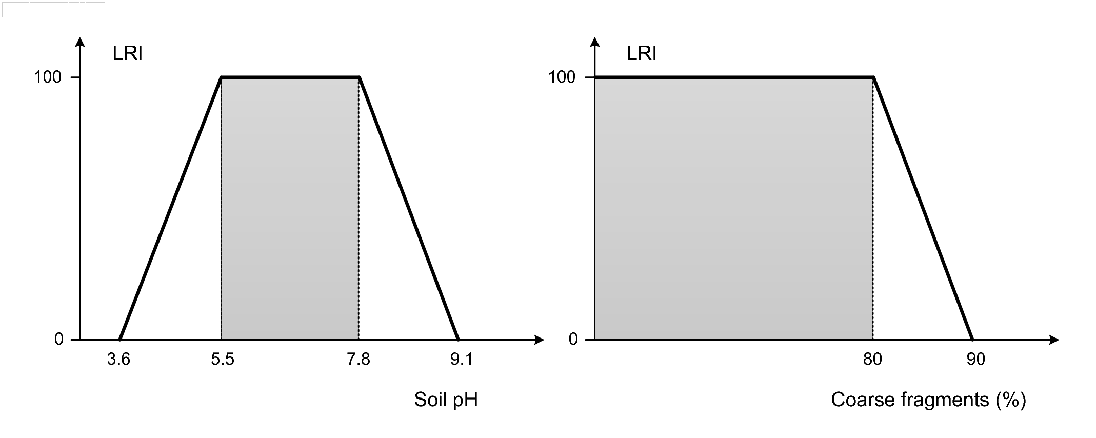
Figure 3.5: Derivation of the Limiting Rooting Index: (left) soil pH values and corresponding LRI, (right) coarse fragments and corresponding LRI. Based on Leenaars et al. (2018) doi: 10.1016/j.geoderma.2018.02.046.
By using the GSIF package, one can determine Limiting Rooting Index, which can be a good indicator of the effective rooting depth. Consider the following soil profile from Nigeria (Leenaars 2014):
## sample profile from Nigeria (ISRIC:NG0017):
UHDICM = c(0, 18, 36, 65, 87, 127)
LHDICM = c(18, 36, 65, 87, 127, 181)
SNDPPT = c(66, 70, 54, 43, 35, 47)
SLTPPT = c(13, 11, 14, 14, 18, 23)
CLYPPT = c(21, 19, 32, 43, 47, 30)
CRFVOL = c(17, 72, 73, 54, 19, 17)
BLD = c(1.57, 1.60, 1.52, 1.50, 1.40, 1.42)*1000
PHIHOX = c(6.5, 6.9, 6.5, 6.2, 6.2, 6.0)
CEC = c(9.3, 4.5, 6.0, 8.0, 9.4, 10.9)
ENA = c(0.1, 0.1, 0.1, 0.1, 0.1, 0.2)
EACKCL = c(0.1, 0.1, 0.1, NA, NA, 0.5)
EXB = c(8.9, 4.0, 5.7, 7.4, 8.9, 10.4)
ORCDRC = c(18.4, 4.4, 3.6, 3.6, 3.2, 1.2)
x <- LRI(UHDICM=UHDICM, LHDICM=LHDICM, SNDPPT=SNDPPT,
   SLTPPT=SLTPPT, CLYPPT=CLYPPT, CRFVOL=CRFVOL,
   BLD=BLD, ORCDRC=ORCDRC, CEC=CEC, ENA=ENA, EACKCL=EACKCL,
   EXB=EXB, PHIHOX=PHIHOX, print.thresholds=TRUE)
x
#> [1] TRUE TRUE TRUE TRUE TRUE TRUE
#> attr(,"minimum.LRI")
#> [1] 35.0 29.5 47.0 54.5 73.0 61.5
#> attr(,"most.limiting.factor")
#> [1] "tetaS" "tetaS" "tetaS" "tetaS" "tetaS" "tetaS"
#> attr(,"thresholds")
#> attr(,"thresholds")$ERscore1
#>  [1] 100.0  80.0  50.0   0.0  95.0  40.0  40.0   5.5   7.8   1.5  10.0
#> [12]   1.0  35.0   2.5 150.0 150.0
#>
#> attr(,"thresholds")$ERscore2
#>  [1]   0.00  90.00  30.00   0.35 100.00  60.00  60.00   3.62   9.05   6.75
#> [11]  25.00   5.00  85.00   6.50 750.00 750.00
#>
#> attr(,"thresholds")$Trend
#>  [1]  0 -1  1 -1 -1 -1 -1  1 -1 -1 -1 -1 -1 -1 -1 -1
#>
#> attr(,"thresholds")$Score
#>  [1] 20 20 20 20 20 20 20 20 20 20 20 20 20 20 20 20
#>
#> attr(,"thresholds.names")
#> attr(,"thresholds.names")$variable
#>  [1] "range"    "CRFVOL"   "tetaS"    "BLD.f"    "SNDPPT"   "CLY.d"
#>  [7] "SND.d"    "PHIHOX.L" "PHIHOX.H" "ECN"      "ENA.f"    "ENA"
#> [13] "EACKCL.f" "EACKCL"   "CRB"      "GYP"
## Most limiting: BLD.f and CRFVOL, but nothing < 20
where UHDICM and LHDICM are the upper and lower horizon depth in cm,
SNDPPT, SLTPPT and CLYPPT are the sand, silt and clay content in
percent, CRFVOL is the volume percentage of coarse fragments (>2 mm),
BLD is the bulk density in t/m\(^3\), ORCDRC is the soil organic carbon
concentration in permille or g/kg, ECN is the electrical conductivity in dS/m,
CEC is the Cation Exchange Capacity in cmol/kg (centi-mol per kilogram), ENA is the exchangable Na
in cmol/kg, EACKCL is the exchangeable acidity in cmol/kg, EXB is the exchangeable
bases in cmol/kg, PHIHOX is the soil pH in water suspension, CRB is the
CaCO\(_3\) (carbonates) in g/kg, GYP is the CaSO\(_4\) (gypsum) in g/kg, and tetaS
is the volumetric percentage of water.
For this specific profile, the most limiting soil property is tetaS, but
because none of the soil properties got <20 points, we can conclude
that the maximum rooting depth is >180 cm. Note that the threshold values in
the LRI function used to derive Limiting Rootability scores are set
based on common soil agricultural productivity tresholds (e.g. for
maize; see also Fig. 3.5), and can be adjusted via the
thresholds argument. The computation is done per list of soil layers
(minimum three) to account for textural changes i.e. sudden changes in
sand and clay content and for the limiting layers such as layer
saturated with water. To determine further the effective rooting depth we can run:
sel <- x==FALSE
if(!all(sel==FALSE)){
  UHDICM[which(sel==TRUE)[1]]
} else {
  max(LHDICM)
}
#> [1] 181

xI <- attr(x, "minimum.LRI")
## derive Effective rooting depth:
ERDICM(UHDICM=UHDICM, LHDICM=LHDICM, minimum.LRI=xI, DRAINFAO="M")
#> [1] 100
3.3 Chemical soil properties
3.3.1 Soil organic carbon
Organic carbon is a soil property of great current global interest (Smith, Falloon, and Kutsch 2004; Pete Smith and Kutsch 2010; Panagos et al. 2013). It is commonly recognized and used as a key indicator of soil health. The amount of carbon present in the soil, and particularly in topsoil horizons, is grossly indicative of potential productivity for crops. Amounts of organic carbon throughout the profile influence soil structure, permeability, porosity, bulk density, water holding capacity, nutrient retention and availability and, consequently, overall soil health. The ability of soils to sequester significant quantities of atmospheric carbon is of considerable interest as a potential mechanism for mitigating the adverse effects of increases in green house gasses in the atmosphere (Smith, Falloon, and Kutsch 2004; Conant et al. 2010; Scharlemann et al. 2014). Consequently, soil organic carbon is probably the soil property of greatest current interest and utility from the point of view of global mapping, and interpretation, of soil properties.
The dry combustion method (Leco at 1000°C) is based on thermal oxidation of both mineral carbon (IC) and organic carbon by means of a furnace. It is a reliable method for the determination of the soil organic carbon when IC is removed through combustion at low temperature prior to combustion at high temperature. Dry combustion is considered to ensure oxidation of all organic carbon, and is considered an accurate method which has been used in many studies as a reference method against which to calibrate other methods (Grewal, Buchan, and Sherlock 1991; Meersmans, Van Wesemael, and Van Molle 2009; Bisutti, Hilke, and Raessler 2004). A global estimate of the probability distribution of soil organic carbon is shown in Fig. 3.6.
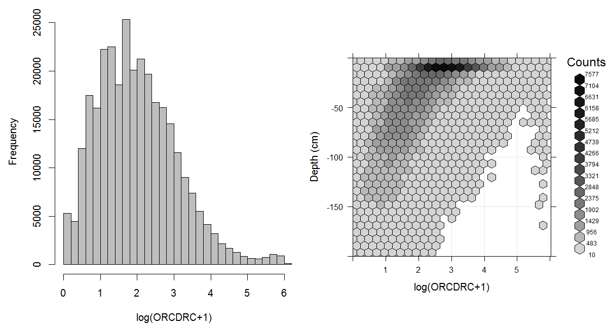
Figure 3.6: Histogram and soil-depth density distribution for a global compilation of measurements of soil organic carbon content (ORCDRC) in permilles. Based on the records from WOSIS (http://www.earth-syst-sci-data.net/9/1/2017/). The log-transformation is used to ensure close-to-normal distribution in the histogram.
Total organic carbon can be determined directly or indirectly. Direct determination includes removal of any carbonates present by treating the soil with hydrochloric acid. Indirect determination consists of applying an empirical correction to the total carbon content to account for the inorganic carbonates present.
Examples of studies that have used dry combustion for calibrating other methods of analyzing organic carbon include Kalembasa and Jenkinson (1973; Grewal, Buchan, and Sherlock 1991; Soon and Abboud 1991; Wang, Smethurst, and Herbed 1996; Konen et al. 2002; Brye and Slaton 2003; Mikhailova, Noble, and Post 2003; Bisutti, Hilke, and Raessler 2004; Jankauskas et al. 2006; De Vos et al. 2007) and Meersmans, Van Wesemael, and Van Molle (2009). It is possible to produce regression equations to permit conversion of results for organic carbon produced by one method into equivalent values into a specified reference method (generally dry combustion). However, local calibration equations that reflect differences in soils on a regional basis are usually needed. It is not possible to provide a single universal equation suitable for use everywhere to convert organic carbon values produced using other methods of analysis to equivalent values in the reference method of dry combustion.
3.3.2 Soil pH
Soil pH is of interest for global soil mapping because it is one of the more widely available and easily interpreted chemical measures of the health and productivity of the soil. pH provides an indication of base status of the soil which influences nutrient availability, mobility of both beneficial and detrimental ions and the ecology of micro-organisms within the soil. For most crops and agricultural uses, a pH in the range of 5.5 to 7.5 is optimal (considering the agricultural productivity of soil). Low pH is associated with acidic conditions and with increased mobility of toxic ions such as aluminium iron and even acid sulphates. High pH is associated with reduced availability of phosphorus and at higher levels with alkaline conditions that impede water uptake by plants. A global estimate of the distribution of the soil pH is shown in Figs. 3.7 and 3.8.
PH index approximates concentration of dissolved hydrogen ions (H\(_3\)O\(^+\)) in a soil suspension. It is estimated as the negative decimal logarithm of the hydrogen ion activity in a soil suspension. As a single measurement, pH describes more than relative acidity or alkalinity. It also provides information on nutrient availability, metal dissolution chemistry, and the activity of microorganisms (Miller and Kissel 2010).
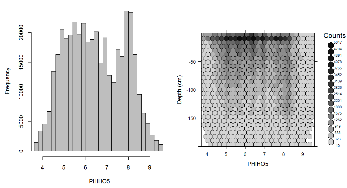
Figure 3.7: Histogram and soil-depth density distribution for a global compilation of measurements of soil pH (suspension of soil in H2O). Based on the records from WOSIS (http://www.earth-syst-sci-data.net/9/1/2017/).
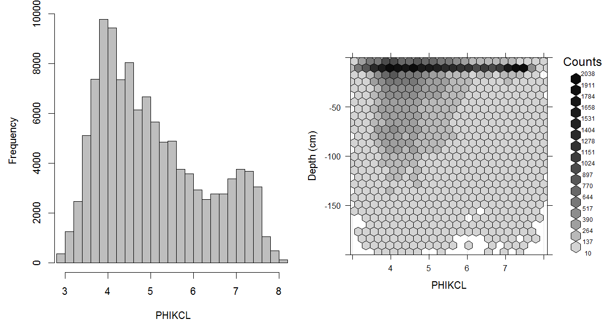
Figure 3.8: Histogram and soil-depth density distribution for a global compilation of measurements of soil pH (suspension of soil in KCl). Based on the records from WOSIS (http://www.earth-syst-sci-data.net/9/1/2017/).
The standard reference method for reporting pH is ISO 10390:2005. This standard specifies an instrumental method for the routine determination of pH using a glass electrode in a 1:5 (volume fraction) suspension of soil in water (pH in H\(_2\)O), in potassium chloride solution (pH in KCl) or in calcium chloride solution (pH in CaCl\(_2\)).
The most common method for analyzing pH in North America is a 1:1 soil/water suspension (Miller and Kissel 2010). Adopting ISO 10390:2005 as a standard with its specification of pH measured in a 1:5 suspension of soil in water requires US values to be converted from 1:1 soil/water to 1:5 soil/water equivalent values.
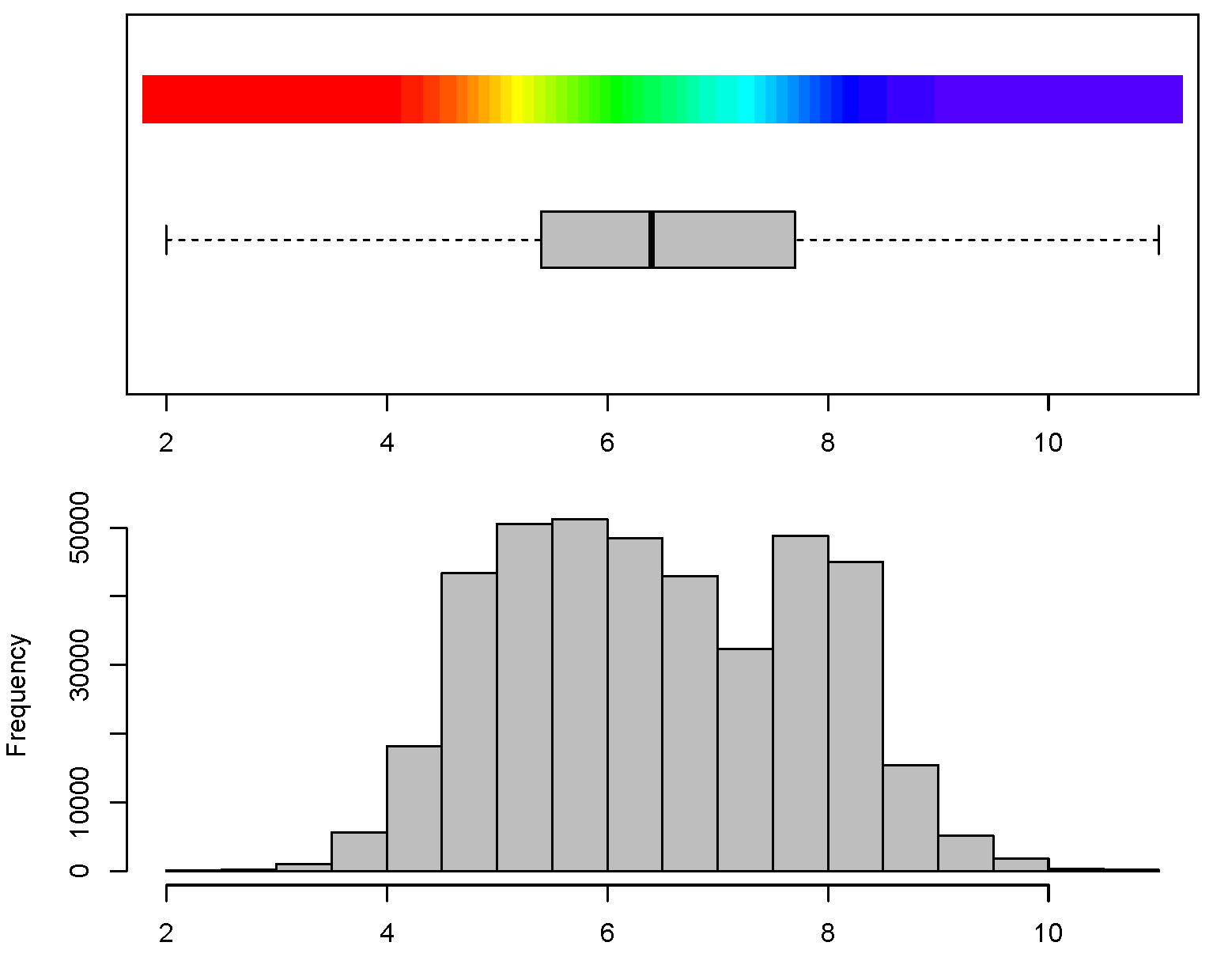
Figure 3.9: Histogram for soil pH and connected color legend available via the GSIF package. Color breaks in the legend have been selected using histogram equalization (i.e. by using constant quantiles) to ensure maximum contrast in the output maps.
The ratio of soil to water in a suspension has a net effect of increasing the pH with a decrease in the soil/water ratio. Davis (1943) has shown that decreasing the soil/water ratio from 10:1 to 1:10 resulted in an increase of 0.40 pH units. Values for pH computed using methods with a lower ratio of soil to water (e.g. 1:1 or 1:2.5) will generally be lower than equivalent values for pH in 1:5 water. Several authors have demonstrated that fitting quadratic or curvilinear functions to soil pH data produces regression equations with higher coefficients of determination than those obtained from a linear fit (Aitken and Moody 1991; Miller and Kissel 2010). For example, Brennan and Bolland (1998) have estimated that (at least in Southwestern Australia) pH in CaCl\(_2\) can be estimated from the pH 1:5 water by using a simple conversion:
ph_h2o = 7.2
0.918*ph_h2o-0.3556
#> [1] 6.25
This model fitted explains 94% of variation in the values of pH CaCl\(_2\) (R-square=0.9401).
Soil pH varies with season and soil moisture content, with higher pH values associated with wetter soils and winter conditions and lower pH values with drier soils and summer conditions (Miller and Kissel 2010). The effects of both temporal variation in pH and variation due to different analytical methods means that differences in pH of less than some specified range (e.g. ±0.3 units) may not be meaningful in the context of predictions made using noisy legacy soils data analyzed using a variety of different analytical methods. Consequently, it is not necessary or beneficial to report pH with a precision greater than ±0.1 unit. Natural variation of pH in soils is over a range of 2–11 with a standard deviation of 1.4. Note also that pH follows a close-to-normal distribution, although it is often argued that, locally, it can show bimodal or even trimodal peaks (Fig. 3.9).
3.3.3 Soil nutrients
Nutrients are chemical elements or substances essential for the growth of plants. The most essential elements important for the growth of plants are carbon, hydrogen and oxygen. Other essential elements can be separated into macro-nutrients (>100 \(\mu\)g or >100 ppm) and micro-nutrients (<100 ppm), although there is no strict border between the two (Harpstead, Sauer, and Bennett 2001; Hengl, Leenaars, et al. 2017). Some macro-nutrients of global importance for soil management and protection are (http://en.wikipedia.org/wiki/Plant_nutrition):
Nitrogen (N) — Nitrogen is often considered synonymous with soil fertility. Controls leafy growth. Occurs in soil as nitrates (e.g. NO\(_3\), NO\(_2\)).
Phosphorus (P) — High phosphorus deficiency may result in the leaves becoming denatured and showing signs of necrosis. Occurs in the form of phosphates.
Potassium (K) — Potassium deficiency may result in higher risk of pathogens, wilting, chlorosis, brown spotting, and higher chances of damage from frost and heat.
Sulfur (S) — Symptoms of deficiency include yellowing of leaves and stunted growth. Occurs in soil in the form of sulfate salts (SO\(_4\)).
Calcium (Ca) — Calcium is involved in photosynthesis and plant structure. Calcium deficiency results in stunting. Occurs in the form of calcium carbonates (CaCO\(_3\)).
Magnesium (Mg) — Magnesium is also an important part of chlorophyll. Magnesium deficiency can result in interveinal chlorosis.
Apart from macro- and micro-nutrients important for plant growth, there is an increasing interest in the distribution of heavy metals in soils, especially ones that are considered toxic or dangerous for human health. Some common heavy metals of interest for soil management and soil protection in developed industrial and / or developing countries are Lead (Pb), Arsenic (As), Zinc (Zn), Cadmium (Cd), Nickel (Ni), Copper (Cu), and Aluminium (Al) (Markus and McBratney 2001; Reimann et al. 2011; Morel et al. 2005; Rodríguez-Lado et al. 2013; Hengl, Leenaars, et al. 2017).
Macro- and micro-nutrients and heavy metals are measured and mapped in parts per million or \(\mu\)g per kg of soil. The AfSIS project, provides a good example of mapping macro- and micro-nutrients over a large area (Hengl, Leenaars, et al. 2017). The problem with mapping such chemical soil properties, however, is that they are highly dynamic. For example, nitrogen, phosphorus, and potassium are highly mobile nutrients. Their concentration changes from month to month, even from day to day so that space-time models (2D-T or 3D-T) need to be developed and the amount of analysis / storage needed can easily escalate.
3.4 Physical and hydrological soil properties
3.4.1 Coarse fragments
Soil texture is connected with soil granulometry or the composition of the particle sizes, typically measured as volume percentages. The most common subdivision of soil granulometry is (Shirazi, Boersma, and Johnson 2001):
Fine earth (<2 m)
1.1 sand (coarser particles in the fine earth),
1.2 silt (medium size particles),
1.3 clay (fine particles <2 \(\mu\)m),
Coarse fragments (>2 mm)
2.1 gravel (2 mm to 8 cm),
2.2 stones or boulders (>8 cm),
Coarse fragments occupy volume in the soil matrix, reducing water and nutrient availability as well as influencing rooting depth and workability. We elect to produce maps of coarse fragment content because many assessments, such as total stocks of carbon or available water, are volumetric based and require knowledge of the volume of non-soil materials throughout the profile. This information is required to support calculations of the total volume of the fine earth fraction that is available to hold water or retain organic carbon. Without some estimate of the volume of the soil occupied by solid particles larger than 2 mm, it would not be possible to compute volumetric estimates of stocks of soil carbon or available moisture for fine earth soil.
Coarse fragments include stones as well as gravel (hard and soft nodules) and the attribute is defined as consisting of all mineral particles with a size exceeding 2 mm. Coarse fragment content is most commonly expressed in volume fraction (volume percentage) of the horizon, layer or sample considered. Laboratory analyses tend to be applied to the fine earth fraction of the soil only and commonly omit consideration of the coarse fragment content. Data for coarse fragment content are generally derived from descriptive field observations on soil layer morphology. Those descriptions generally express the content of coarse fragments by class values or categories as for example ‘frequent stones’ indicating an estimated volumetric content of 15–40% according to the FAO guidelines of 1977 (similar to ‘many stones’ according to SOTER conventions and the FAO guidelines of 2006). Because coarse fragment content is most frequently based on generalized visual field estimates, and is often lacking in legacy soil descriptions, it is not reasonable to predict or present estimates of coarse fragment content with a precision greater than 1–5%.
Note that the uncertainty associated with coarse fragment content, propagated from the field observed class values, has significant impact on estimations of the volumetric totals of attributes assessed and mapped for the fine earth fraction (see also chapter 7). Whilst a 1 meter deep soil, with a bulk density of 1.5 tonne per cubic-metre and an organic carbon content of 10 g per kg, contains 150 tonnes organic carbon, a similar soil with bulk density adjusted for the presence of ‘frequent stones’ contains only 90–127.5 tonnes organic carbon. Despite the inaccuracy of the data for field observed coarse fragments content, it is strongly recommended to collect and compile these data as completely as possible because of their relevance for estimating whole soil bulk density, total volume and volume of the fine earth fraction alone.
The possible nature (and size) of coarse fragments is highly variable (quartz, carbonate, iron, basalt) with consequent variable manageability and variable characteristics such as breakability, solubility, bulk density, etc. Where the coarse fragment content is dominant (>80%), approaching 100%, rootability is near nil which is a determinant for the rooting or effective soil depth and generally also for depth to bedrock. An estimated global distribution of coarse fragments and soil textures is given in Fig. 3.10.
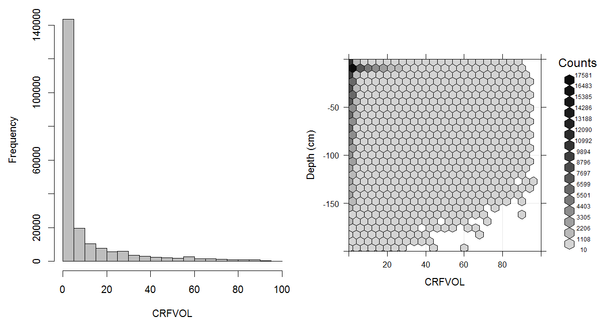
Figure 3.10: Histogram and soil-depth density distribution for a global compilation of measurements of coarse fragments in percent. Based on the records from WOSIS (http://www.earth-syst-sci-data.net/9/1/2017/). This variable in principle follows a zero inflated distribution.
3.4.2 Particle size class distribution: sand, silt and clay
The majority of global soil mapping initiatives elect to predict the spatial distribution of particle size classes (soil texture) because texture controls or influences many mechanical, hydrological and engineering aspects of use of the soil. Soil texture affects how a soil responds to engineering uses such as construction of roads, buildings, dams and other structures, how water infiltrates into the soil and is stored or transmitted through it, how nutrients, chemicals and dissolved substances adhere to surfaces and are retained or transformed and how energy and matter enter into the soil and are stored or transmitted through it. Texture is the fundamental physical and mechanical property of soils and, as such, it is one of the most widely analysed and widely reported soil properties.
The size of particles in the soil varies greatly from less than a 2 \(\mu\)m to several cm’s and occasionally even meters (boulders). This represents a range from 1 \(\mu\)m to 1 million \(\mu\)m. Generally, particle size distribution has been simplified through aggregation or classification. The fine earth fraction (<2 mm) is the soil considered for laboratory analyses. This fine earth is further subdivided into particle size classes including, depending on the guidelines or laboratory concerned, fine and coarse clay, fine and coarse silt and very fine, fine, medium, coarse and very coarse sand. The three major particle size classes of the fine earth fraction though are sand, silt and clay. They are generally reported in units of percent by weight with a precision of ±1%.
Soil texture represents the relative composition of sand, silt, and clay in soil. The particle-size class distribution is usually represented in a texture diagram, relating the percentages of sand, silt, and clay (mass percentage of fine earth) to a texture class (Minasny and McBratney 2001). Particle size distribution has been defined using a number of systems. One of the most widely used systems is the USDA Soil Survey Laboratory Methods Manual (Natural Resources Conservation Service 2004). The USDA definition of particle size classes has also been recommended by FAO for use in the Soil Map of the World (Fig. 3.11). The standard reference method for reporting particle size classes of sand, silt and clay, is as per the USDA Soil Survey Laboratory Methods Manual (Natural Resources Conservation Service 2004, 347). An estimated global distribution of sand, silt, and clay is given in Figs. 3.12, 3.13 and 3.14.
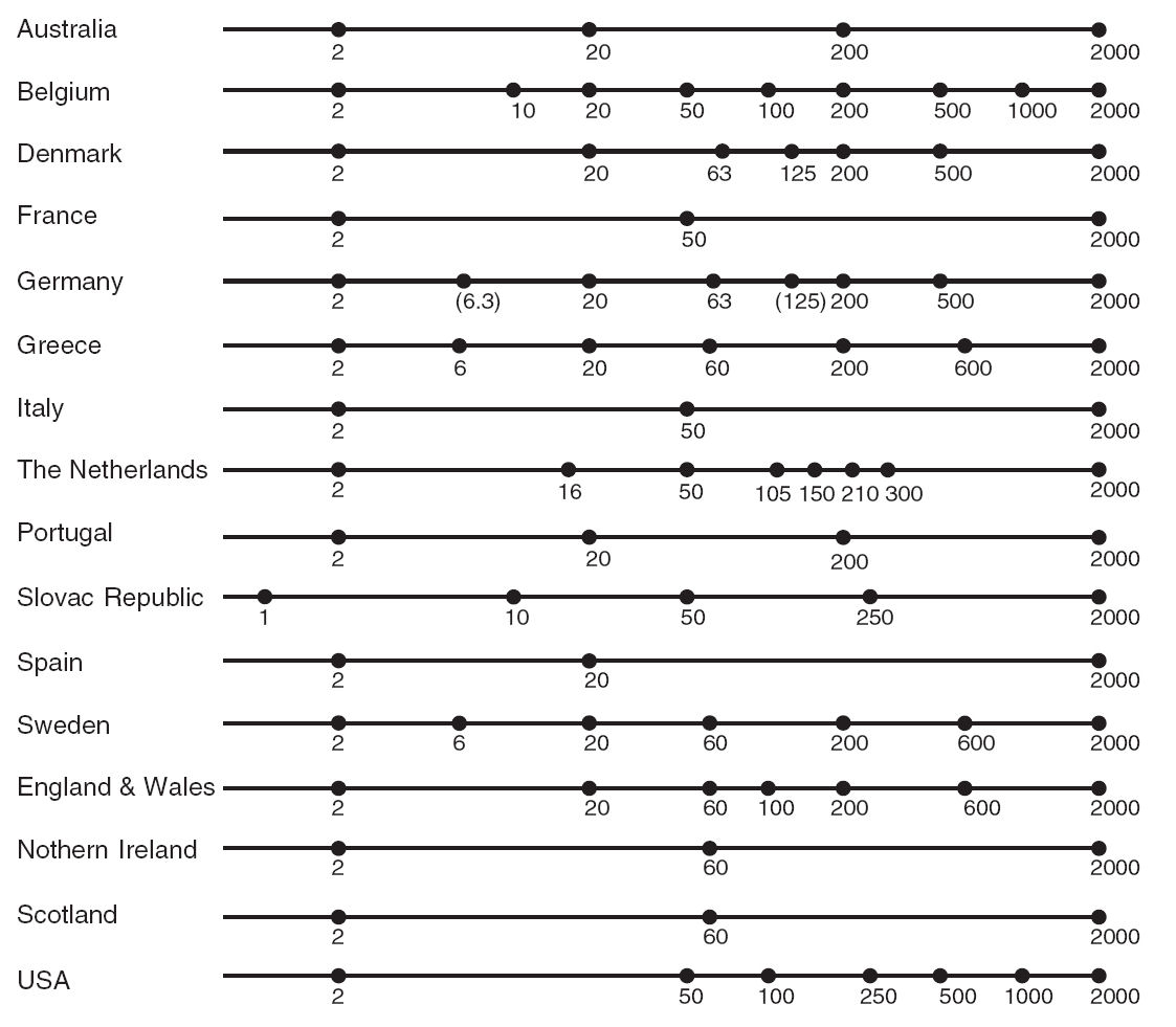
Figure 3.11: Particle size limits used in European countries, Australia and America. Image source: Minasny and McBratney (2001) doi: 10.1071/SR00065.
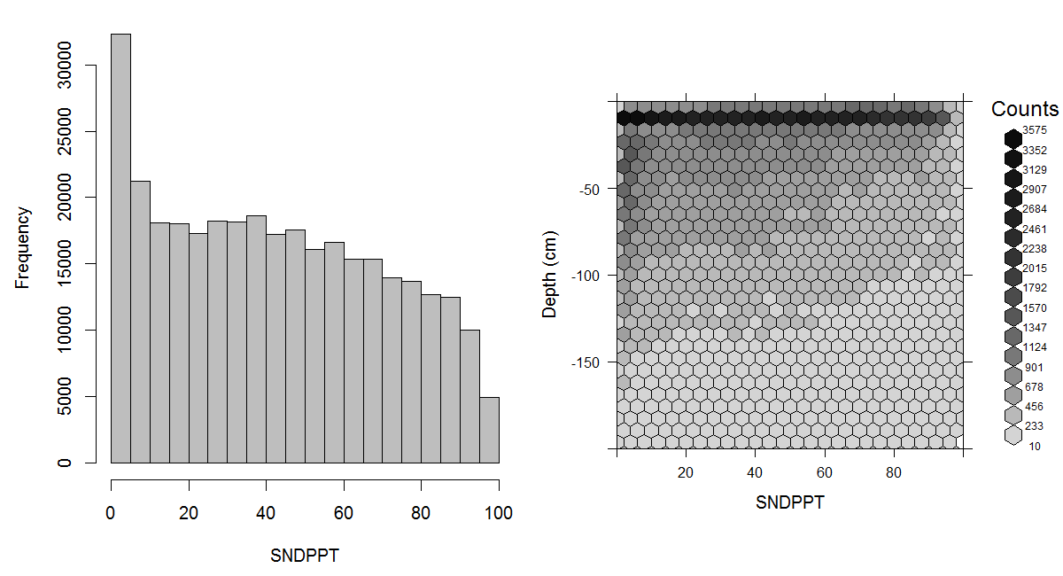
Figure 3.12: Histogram and soil-depth density distribution for a global compilation of measurements of sand content in percent. Based on the records from WOSIS (http://www.earth-syst-sci-data.net/9/1/2017/).
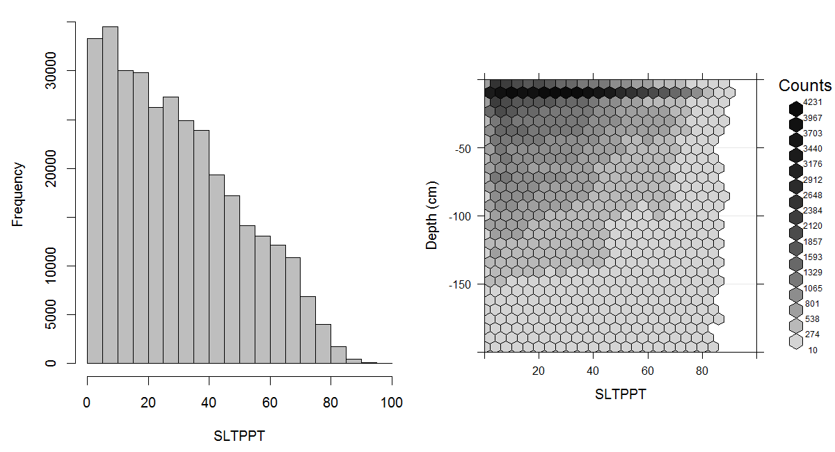
Figure 3.13: Histogram and soil-depth density distribution for a global compilation of measurements of silt content in percent. Based on the records from WOSIS (http://www.earth-syst-sci-data.net/9/1/2017/).
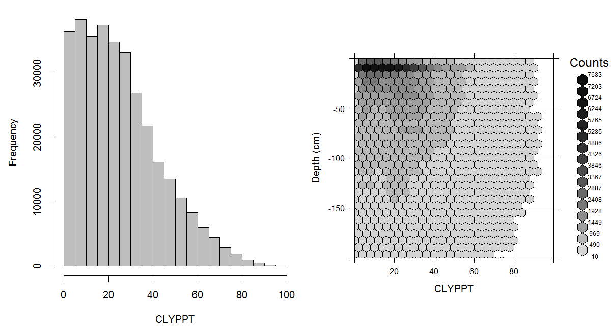
Figure 3.14: Histogram and soil-depth density distribution for a global compilation of measurements of clay content in percent. Based on the records from WOSIS (http://www.earth-syst-sci-data.net/9/1/2017/).
The current standard for particle size classes adopted by FAO for use in the Harmonized World Soil Database is ISO 10390:2005. This standard differs from the USDA definition in defining the size range for silt as 2–63 \(\mu\)m instead of 2–50 \(\mu\)m and sand as 63–2000 \(\mu\)m instead of 50–2000 \(\mu\)m. This is a relatively new standard for FAO which previously adopted the USDA definitions for the digital soil map of the world (Nachtergaele, Van Engelen, and Batjes 2010). These differences in attribute definition cause differences in values reported for soil particle size classes. Differences in values can also arise because of differences in method of analysis (e.g. hygrometer, pipette, laser diffraction, dispersion etc). Most literature on harmonization of soil texture data deals with harmonizing differences in attribute definitions or the reported particle size classes (Fig. 3.11).
Minasny and McBratney (2001) identified two major textural classifications in the world as the International and USDA/FAO systems (Tbl. 3.3). The significant difference between these two was the choice of a threshold value for differentiating silt from sand of 20 \(\mu\)m for the International and 50 \(\mu\)m for the USDA/FAO systems. The new ISO/FAO standard adds an additional difference by changing the threshold value between silt and sand from 50 \(\mu\)m to 63 \(\mu\)m. Another very important difference in attribute definition concerns the Russian system which defines the clay fraction as <1 \(\mu\)m and the fine earth fraction, or the upper limit of the sand fraction, at 1 cm instead of 2 cm.
| Fraction | International | USDA | ISO.FAO |
|---|---|---|---|
| clay | <2 μm | <2 μm | <2 μm |
| silt | 2–20 μm | 2–50 μm | 2–63 μm |
| sand | 20–2000 μm | 50–2000 μm | 63–2000 μm |
Both Nemes et al. (1999) and Minasny and McBratney (2001) investigated options for harmonizing values for sand, silt and clay reported using different systems for classifying particle size fractions. Using a compilation of four large databases consisting of a total of 1620 samples, Minasny and McBratney (2001) developed a single multiple linear regression model for converting between silt fraction based on the international standard of 2–20 \(\mu\)m (\(P_{\mathtt{2-20}}\)) to the 2–50 \(\mu\)m range of the USDA standard (\(P_{\mathtt{2-50}}\)) and vice versa:
\[\begin{equation} \begin{cases} \begin{matrix} \hat P_{\mathtt{2-50}} = & -18.3914 + 2.0971 \cdot P_{\mathtt{2-20}} + 0.6726 \cdot P_{\mathtt{20-2000}} \\ & - 0.0142 \cdot P_{\mathtt{2-20}}^2 - 0.0049 \cdot P_{\mathtt{20-2000}}^2 \end{matrix} & \text{ if } \hat P_{\mathtt{2-50}} > 0 \\ \begin{matrix} \hat P_{\mathtt{2-50}} = & 0.8289 \cdot P_{\mathtt{2-20}} + 0.0198 \cdot P_{\mathtt{20-2000}} \end{matrix} & \text{ if } \hat P_{\mathtt{2-50}} < 0 \end{cases} (\#eq:P2_50) \end{equation}\]where \(P_{\mathtt{20-2000}}\) is the international sand fraction. This conversion is fairly accurate since the model explains most of the observed variability in the original values (\(R^2\)=0.823). Together with the conversion of the silt fraction is the conversion of the sand fraction.
Minasny and McBratney (2001) argued that most countries should consider adopting the particle size limits and texture classes of the USDA system. They noted that the 2–50 \(\mu\)m particle size range is usually more useful than the 2–20 \(\mu\)m range for estimating water retention in pedo-transfer functions and observed that translations from one system into another were relatively easy, given improved computing power and algorithms.
Nemes, Schaap, and Leij (1999; Nemes et al. 1999) evaluated four different interpolation methods (log-linear interpolation, fitting a Gompertz curve, spline interpolation, and similarity method) in order to achieve compatibility of particle-size distributions within the European soil hydraulic database HYPRES (http://www.macaulay.ac.uk/hypres/). They introduced a new similarity procedure, which uses an external reference data set that contains a wide variety of reference soil materials, each with 7 or 8 measured particle-size fractions. The procedure involves searching for soil samples in the external reference data set that match the particle-size distribution of the soil to be interpolated. From each search. 10 similar soils are selected that have fractions at the particle size limits similar to the soil under investigation. The arithmetic mean of the fractions of these 10 soils at the specified particle size limit is calculated and assigned as the estimate of the fraction for the soil under investigation.
The HYPRES reference database and the similarity procedures applied to it are appropriate for harmonizing a wide range of soils from a variety of countries and could be used as one of the main methods in a global Soil Reference Library. The generic nature of this conversion approach, and the fact that it does not rely on multiple, locally developed, regression equations, makes it an attractive option for use in harmonization of global particle size data.
3.4.3 Bulk density
Measurement of soil Bulk Density (BLD) is often time consuming and relatively costly. For this reason, it is not analysed and reported for legacy soil profiles as frequently or consistently as many other, more common, soil properties. Consequently, predicting bulk density globally using digital soil mapping methods is fraught with difficulties and uncertainties. However, it is critical to at least attempt to make some kind of estimate of how bulk density varies spatially because we need to know the bulk density of the soil in order to make any estimates of volumetric concentrations of materials such as organic carbon, water or nutrients.
In practice, we need to be able to make estimates of two different types of bulk density, namely the bulk density of the whole soil and the bulk density of the fine earth fraction (particles <2 mm) only. Calculations such as those for total stocks of carbon are first applied using the bulk density of the fine earth fraction only but this value is then reduced in accordance with the volume proportion of the soil that is occupied by coarse fragments greater than 2 mm in size. Bulk density is also of interest for global soil mapping applications because it influences infiltration and movement of water in the soil, penetration of the soil by plant roots and mechanical workability of the soil using farm implements.
Bulk density is the over-dry mass of soil material divided by the total volume. The standard reference method for reporting bulk density is the core method (ISO 11272): the dry bulk density (BD) is the ratio between the mass of oven dry soil material and the volume of the undisturbed fresh sample. The ISO standard defines dry bulk density as the ratio of the oven-dry mass of the solids to the volume (the bulk volume includes the volume of the solids and of the pore space) of the soil. The recommended ISO method (core method) uses steel cylinders of known volume (100 cm\(^3\) and/or 400 cm\(^3\)) that are driven into the soil vertically or horizontally by percussion. Sampling large volumes results in smaller relative errors but requires heavy equipment. The method cannot be used if stones or large roots are present or when the soil is too dry or too hard.
For soils with a high stone or root content or when the soil is too dry or too hard, methods based on the excavation technique are used as an alternative to the core method. In the excavation method a hole on a horizontal surface is dug and then filled with a material with a known density (e.g. sand which packs to a calibrated volume or water separated from the soil material by an elastic membrane) to assess the volume of the hole or the sample taken. The soil obtained from the hole, is oven-dried to remove the water and the oven-dry mass of the total sample is weighed. The volumetric percentage of the coarse fragments needs to be determined and the weight of the coarse fragments assessed, in order to be able to calculate the oven-dry bulk density of the fine earth separately.
The USDA handbook for analytical procedures describes various methods for assessing various types of bulk density. USDA soil data report values for bulk density of the fine earth as well as of the whole earth (including gravel), with the weight assessed oven-dry as well as at field capacity e.g. including water. The latter method relates the weight of moist soil to the volume of moist or oven-dry soil. Experience has shown that organic carbon and texture or clay content predominately influence soil bulk density, even though the nature of the clay (mineralogy) is as important as the percentage content of the clay. Organic carbon and texture information is often available in soil survey reports, while bulk density is often not reported.
Many attempts have therefore been made to estimate soil bulk densities through pedo-transfer functions (PTFs) based on soil organic carbon and texture data (Curtis and Post 1964; Adams 1973; Alexander 1980; Federer, Turcotte, and Smith 1993; Rawls 1983; Manrique and Jones 1991; Bernoux et al. 1998). Heuscher, Brandt, and Jardine (2005) applied a stepwise multiple regression procedure to predict oven-dried bulk density from soil properties using the NRCS National Soil Survey Characterization Data. The database included both subsoil and topsoil samples. An overall regression equation for predicting oven-dried bulk density from soil properties (\(R^2=0.45\), \(P<0.001\)) was developed using almost 47,000 soil samples. Further partitioning of the database by soil suborders improved regression relationships (\(R^2=0.62\), \(P<0.001\)). Of the soil properties considered, the stepwise multiple regression indicated that organic C content was the strongest contributor to bulk density prediction (Heuscher, Brandt, and Jardine 2005). Other significant variables included clay content, water content and to a lesser extent, silt content, and depth.
Bulk density tends to be measured and reported less frequently in legacy data bases and reports than most other commonly measured soil analytical properties. Bulk density is often based on field measurements of in-situ bulk density using the core method. Bulk density of the fine earth fraction alone is measured and reported even less frequently than bulk density for the whole soil (Fig. 3.15).
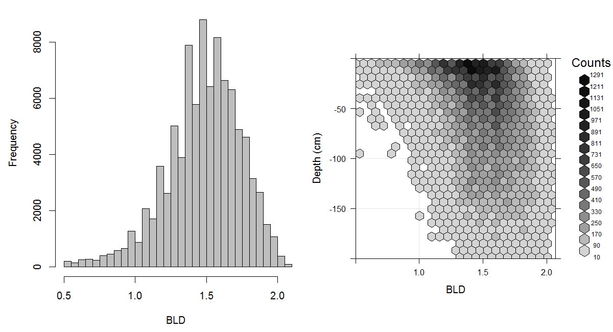
Figure 3.15: Histogram and soil-depth density distribution for a global compilation of measurements of bulk density (tonnes per cubic metre). Based on the records from WOSIS (http://www.earth-syst-sci-data.net/9/1/2017/).
Given that there are more values reported for the bulk density of the whole soil than for the fine earth fraction, we elect to first estimate the bulk density of the whole soil (using appropriate pedo-transfer functions) and then apply corrections to estimate the bulk density of the fine earth fraction, correcting for the effect of course fragments. Correction involves subtracting the volume of coarse fragments from the total volume of soil sampled for assessing bulk density in-situ in the field and then also subtracting the (estimated) weight of coarse fragments from the measured oven-dry weight of the sampled soil.
The revised weight of the fine-earth fraction alone (minus the weight of the coarse fragments) is divided by the adjusted volume of the sample (reduced by the volume of coarse fragments) to obtain an estimate of bulk density for the fine earth fraction alone. This value of density of the fine-earth fraction alone is the one needed to compute estimates of volumetric soil properties, such as total carbon stocks. It is therefore the critical measure of bulk density for reporting concentrations of soil chemical properties. Conversely, bulk density of the whole soil, in situ, is generally of greater use and interest for assessing hydrological behaviours and properties, such as hydraulic conductivity and moisture holding capacity.
Tranter et al. (2007) proposed a conceptual model that incorporated a priori knowledge for predicting soil bulk density from other, more regularly measured, properties. The model considers soil bulk density to be a function of soil mineral packing structures (\(\rho_m\)) and soil structure (\(\Delta \rho\)). Bulk densities were also observed to increase with depth, suggesting the influence of over-burden pressure. Residuals from the \(\rho_m\) model, referred to as \(\Delta \rho\), correlated with organic carbon.
Torri et al. (1994) developed a nomogram for transforming rock fragment content from a by-mass to a by-volume basis and vice versa based on bulk density data. This nomogram facilitates conversion of data on rock fragment content expressed in different units. Most PTFs for predicting bulk density, except those developed by Rawls (1983) and Bernoux et al. (1998), are a function of organic matter i.e. organic carbon content. Although studies conducted by Saini (1966) and Jeffrey (1970) have shown that organic matter has a dominating effect on soil bulk density and that it can be used alone as a good predictor of soil bulk density, it has been observed (e.g. Alexander (1980) and Manrique and Jones (1991)) that, where organic matter is a minor component, soil texture plays a major role in controlling bulk density .
3.4.4 Soil organic carbon stock
Primary soil properties such as organic carbon content, bulk density and coarse fragments can be further used as inputs for estimation of secondary soil properties which are typically not measured directly in the field, or laboratory, and need to be derived from primary soil properties. For instance, consider estimation of the global carbon stock (in permille). This secondary soil property can be derived from a number of primary soil properties (Nelson and Sommers 1982; Sanderman, Hengl, and Fiske 2018) (see Fig. 3.16):
\[\begin{equation} \mathtt{OCS} \; [\mathrm{kg \; m^{-2}}] = \frac{{\mathtt{ORC}}}{{1000}} \; [\mathrm{kg \; kg^{-1}}] \cdot \frac{{\mathtt{HOT}}}{{100}} \; [\mathrm{m}] \cdot \mathtt{BLD} \; [\mathrm{kg \; m^{-3}}] \cdot \frac{{100-\mathtt{CRF} \; [\mathrm{\%}]}}{{100}} \tag{3.1} \end{equation}\]where OCS is soil organic carbon stock, ORC is soil organic carbon
mass fraction in permilles, HOT is horizon thickness in , BLD is
soil bulk density in and CRF is volumetric fraction of coarse
fragments (\(>\) 2 mm) in percent.
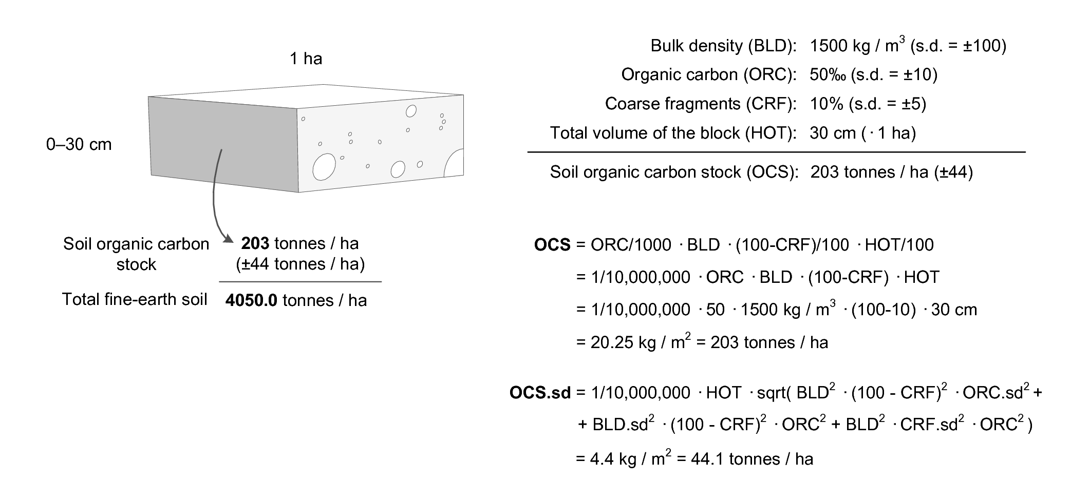
Figure 3.16: Soil organic carbon stock calculus scheme. Example of how total soil organic carbon stock (OCS), and its propagated error, can be estimated for a given volume of soil using organic carbon content (ORC), bulk density (BLD), thickness of horizon (HOT), and percentage of coarse fragments (CRF). Image source: Hengl et al. (2014) doi: 10.1371/journal.pone.0169748. OCSKGM function also available via the GSIF package.
The propagated error of the soil organic carbon stock (Eq.(3.1)) can
be estimated using the Taylor series method (Heuvelink 1998) i.e. by
using the standard deviations of the predicted soil organic carbon
content, bulk density and coarse fragments, respectively
(Fig. 3.16). OCS values can be derived for
all depths / horizons, then aggregated to estimate the total stock for
the whole profile (e.g. 0–2 m).
The formulas to derive soil organic carbon stock and the propagated uncertainty as implemented in the GSIF package are e.g.:
Area <- 1E4  ## 1 ha
HSIZE <- 30 ## 0--30 cm
ORCDRC <- 50  ## 5%
ORCDRC.sd <- 10  ## +/-1%
BLD <- 1500  ## 1.5 tonnes per cubic meter
BLD.sd <- 100  ## +/-0.1 tonnes per cubic meter
CRFVOL <- 10  ## 10%
CRFVOL.sd <- 5  ## +/-5%
x <- OCSKGM(ORCDRC, BLD, CRFVOL, HSIZE, ORCDRC.sd, BLD.sd, CRFVOL.sd)
x  ## 20.25 +/-4.41 kg/m^2
#> [1] 20.2
#> attr(,"measurementError")
#> [1] 4.41
#> attr(,"units")
#> [1] "kilograms per square-meter"
x[[1]] * Area / 1000 ## in tonnes per ha:
#> [1] 202
A more robust way to estimate the propagated uncertainty of deriving
OCS would be to use geostatistical simulations e.g. derive standard
error from a large number of realizations (e.g. >100) that incorporate
spatial and vertical correlations. Because, in the case of soil mapping,
we are often dealing with massive data sets, running geostatistical
simulations for millions of pixels is currently not a feasible option.
3.4.5 Available Water Capacity
The available water holding capacity (AWC) is a complex soil property. It is basically a soil or land quality (Food, Agriculture Organization of the United Nations. Soil Resources, and Service 1977), that provides valuable information about the capacity of the soil to hold water, particularly water that is potentially available for root uptake by plants and vegetative transpiration (Fig. 3.17). In practice, AWC is land cover specific. The water available for root uptake depends on the soil properties that determine rootability or rooting depth as genetically required by the currently active vegetative land cover.
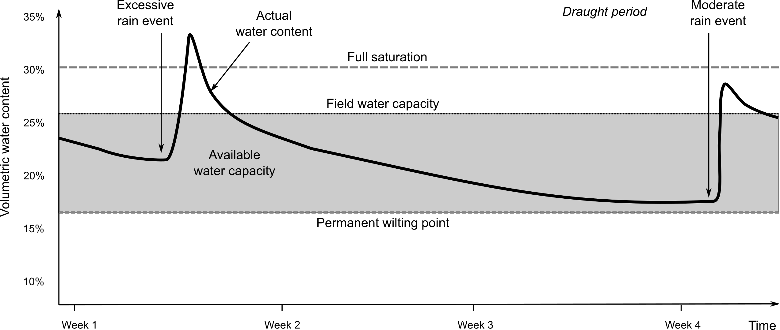
Figure 3.17: Example of a soil-water plot. Actual water content can be measured using soil moisture probes i.e. automated sensor networks.
The water available for root uptake also depends on the pressure head that the vegetative land cover can generate or bridge between the pressure in the atmosphere and the pressure in the soil matrix. E.g. cotton can still extract water at -2500 kPa (pF 4.4) while pepper wilts at -350 kPa (pF 3.5). The ability of a soil to accept and store water has implications beyond simply the capacity to support plant growth. It also affects how a soil responds to hydrological events such as rainfall, snowmelt and runoff. Soils that can rapidly absorb and retain significant amounts of rainfall act as a buffer reducing rapid runoff and flooding. Soils that have a limited ability to accept and store rainfall contribute to rapid runoff with increased chances of erosion and flooding. Models of crop growth, runoff, erosion and flooding all have requirements for location-specific information about available water capacity.
Values for AWC are preferably assessed for the fine earth fraction per depth interval and expressed as volumetric fraction. This value can be corrected for the gravel content of the depth interval and summed up over the interval. Preferably, the values for volumetric AWC of the fine earth fraction per depth interval are derived from values for water content at specific water tensions (e.g. at pF 0.1, 2, 2.5, 3, 4.2, 4.5). For pragmatic reasons though the permanent wilting point is set at -1500 kPa (or pF 4.2).
The standard reference method adopted by GSIF and LandGIS for reporting available
water capacity is as per the USDA Soil Survey Laboratory Methods Manual
(Natural Resources Conservation Service 2004, 137). Calculation of the Water Retention Difference
(WRD) is considered the initial step in the approximation of the
available water capacity (AWC). WRD is a calculated value that denotes
the volume fraction for water in the whole soil that is retained between -1500 kPa suction and an upper limit of usually -33 or -10 kPa suction (pF 2.5 or pF 2)
(Natural Resources Conservation Service 2004, 137). The upper limit (lower suction) is selected so
that the volume of water retained approximates the volume of water held
at field capacity. The -33 and -1500 kPa gravimetric water contents are then
converted to a whole soil volume basis by multiplying by the oven dry
bulk density of the fine earth fraction (Db33) and adjusting downward
for the volume fraction of rock fragments, if present, in the soil.
“The development of hydraulic PTFs has become an industry” (Minasny 2007). Results of such research have been reported widely, including in the USA (Rawls, Gish, and Brakensiek 1991), UK, the Netherlands (Wösten, Fi, and Jansen 1995), and Germany. Research has attempted to correlate particle size distribution, bulk density and organic matter content with water content at field capacity (FC, \(\theta\) at -33 kPa), permanent wilting point (PWP, \(\theta\) at -1500 kPa), and available water content (AWC = FC - PWP) (Minasny 2007). Gijsman, Thornton, and Hoogenboom (2007) reported that “many PTFs for estimating soil hydraulic properties have been published already” (see overviews by Rawls, Gish, and Brakensiek (1991), Timlin et al. (1996) and Wösten, Pachepsky, and Rawls (2001)). Timlin et al. (1996) reported 49 methods and estimated that these cover only about 30% of the total. Gijsman, Thornton, and Hoogenboom (2007) compared eight methods for all the soil classes that make up the texture triangle. They went through the triangle in steps of sand, silt and clay and determined the estimated values of wilting point or lower limit of plant extractable water (LL), field capacity or the drained upper limit (DUL), and soil saturation (SAT). They finally concluded that none of the methods were universally good. The best method in the comparison of Gijsman, Thornton, and Hoogenboom (2007) was Saxton et al. (1986), closely followed by Rawls and Brakensiek (1982).
Alterra institute in collaboration with ISRIC validated the PTF developed by Hodnett and Tomasella (2002) on the basis of the data present in the Africa Soil Profiles database (Leenaars 2014) to predict tension specific volumetric water content (Wösten et al. 2013) to assess WRD. Jagtap et al. (2004) developed an approach that does not fit a mathematical equation through the data, but rather compares the soil layer for which the key soil water contents of lower limit (LL), drained upper limit (DUL), and soil saturation (SAT), have to be estimated with all layers in a database of field-measured soil-water-retention data. The layer that is most similar in texture and organic carbon concentration is considered to be the ‘nearest neighbor’ among all the layers in the database and its soil-water-retention values are assumed to be similar to those that need to be estimated. To avoid making estimated soil-water-retention values dependent on only one soil in the database, the six ‘nearest neighbors’ are used and weighted according to their degree of similarity (Jagtap et al. 2004). This is a non-parametric procedure, in the sense that it does not assume a fixed mathematical relationship between the physical properties and the water holding properties of soils. The similarity method to convert soil particle size fraction data proposed by Nemes et al. (1999; Nemes, Schaap, and Leij 1999) is a direct analogue of this similarity method of Jagtap et al. (2004) for soil hydraulic properties.
Zacharias and Wessolek (2007) identified three different approaches for deriving the WRD from more easily available parameters as:
Point-based estimation methods: estimating the water content of selected matric potentials from predictors such as the percentage of sand, silt, or clay, the amount of organic matter, or the bulk density (e.g. Rawls and Brakensiek (1982)).
Semi-physical approach: deriving the WRD from information on the cumulative particle size distribution (Arya and Paris 1981); theoretically, this approach is based on the similarity between cumulative particle size distribution and water retention curves. The water contents are derived from the soil’s predicted pore volume and the hydraulic potentials are derived from capillarity relationships.
Parameter estimation methods: using multiple regression to derive the parameters of an analytical closed-form equation for describing the WRD, using predictors such as the percentage of sand, silt, and clay, the amount of organic matter, or the bulk density (e.g. Van Genuchten (1980; Wösten et al. 1999, 2013)).
Zacharias and Wessolek (2007) concluded that approach (1) has the disadvantage that it uses a large number of regression parameters depending on the number of WRD sampling points, which makes its use in the mathematical modeling more difficult; while for approach (2) very detailed information about the particle size distribution is required. They therefore preferred use of (3) the parameter estimation methods.
Zacharias and Wessolek (2007) also observed that pedo-transfer functions that do not consider soil organic matter are rare and gave the following examples. Hall et al. (1977) developed point-based regression equations using soil texture and bulk density (only for subsoils) for British soils. Oosterveld and Chang (1980) developed an exponential regression equation for Canadian soils for fitting the relationship between clay and sand content, depth of soil, and moisture content. Equations to estimate the WRC from mean particle diameter and bulk density have been proposed by Campbell and Shiozawa (1989). Williams, Ross, and Bristow (1992) analyzed Australian data sets and developed regression equations for the relationship between soil moisture and soil texture, structure information, and bulk density including variants for both the case where there is available information on soil organic matter and where the soil organic matter is unknown. Rawls and Brakensiek (1989) reported regression equations to estimate soil water retention as a function of soil texture and bulk density. Canarache (1993) developed point based regression equations using clay content and bulk density for Romanian soils. More recently, Nemes, Schaap, and Wösten (2003) developed different PTFs derived from different scales of soil data (Hungary, Europe, and international data) using artificial neural network modeling including a PTF that uses soil texture and bulk density only.
Zacharias and Wessolek (2007) developed two different regression equations largely based on the percentage of sand in a soil as follows:
\[\begin{equation} \begin{cases} \begin{matrix} \theta_r = 0 \\ \theta_s = 0.788 + 0.001 \cdot {\mathtt{clay}} -0.263 \cdot D_b \\ \ln(\alpha) = -0.648 + 0.023 \cdot {\mathtt{sand}} + 0.044 \cdot {\mathtt{clay}} -3.168 \cdot D_b \\ n = 1.392- 0.418\cdot {\mathtt{sand}}^{-0.024} + 1.212\cdot {\mathtt{clay}}^{-0.704} \end{matrix} & \text{ if } {\mathtt{sand}} < 66.5\% \\ \hline \begin{matrix} \theta_r = 0 \\ \theta_s = 0.890 + 0.001 \cdot {\mathtt{clay}} -0.332 \cdot D_b \\ \ln(\alpha) = -4.197 + 0.013 \cdot {\mathtt{sand}} + 0.076 \cdot {\mathtt{clay}} -0.276 \cdot D_b \\ n = 2.562 - 7 \cdot 10^{-9} \cdot {\mathtt{sand}} + 3.750\cdot {\mathtt{clay}}^{-0.016} \end{matrix} & \text{ if } {\mathtt{sand}} > 66.5\% \end{cases} \tag{3.2} \end{equation}\]The regression coefficients from these models were almost identical to those reported by Vereecken, Maes, and Feyen (1989) (i.e. \(\theta_s = 0.81 + 0.001 \cdot {\mathtt{clay}} - 0.283 \cdot D_b\)) for a different data set, adding further credibility to their general applicability. Zacharias and Wessolek (2007) recommended using the PTFs of Vereecken, Maes, and Feyen (1989) if data on soil organic matter were available.
Empirical equations developed by Williams, Ross, and Bristow (1992) for the prediction of the constants \(A\) and \(B\) in the Campbell function have been widely used in Australia and elsewhere. These regression equations require particle size distribution, field texture and bulk density inputs as follows:
\[\begin{equation} \begin{split} A =& 1.996 + 0.136 \cdot \ln({\mathtt{clay}}) - 0.00007 \cdot {\mathtt{fsand}} + \\ & + 0.145\cdot \ln({\mathtt{silt}}) + 0.382 \cdot \ln({\mathtt{TEXMHT}}) \end{split} \end{equation}\] \[\begin{equation} B = -0.192 + 0.0946\cdot \ln({\mathtt{TEXMHT}}) - 0.00151\cdot \mathtt{fsand} \end{equation}\]where \(\mathtt{clay}\) (<0.002 mm), \(\mathtt{fsilt}\) (0.02–0.20 mm), and \(\mathtt{sand}\) (0.002–0.02 mm) are expressed in %; \(\mathtt{TEXMHT}\) is texture group from 1–6 as defined by Northcote in Peverill, Sparrow, and Reuter (1999).
Cresswell et al. (2006) demonstrated applicability of the Williams, Ross, and Bristow (1992) method for French soils and confirmed that the approach of assuming a Campbell SWC model and empirically predicting the slope and air entry potential has merit. They concluded that the empirical regression equations of Campbell appeared transferable to different data sets from very different geographical locations. They provided regression equations for all samples and stratified by horizon type that had R-square values ranging from 0.81 to 0.91.
Cresswell et al. (2006) further suggested a strategy for achieving adequate coverage of soil hydraulic property data for France that included an efficient sampling strategy based on the use of functional horizons (Bouma 1989), and a series of reference sites where soil hydraulic properties could be measured comprehensively. They argued that the functional horizon method recognizes the soil texture class of the horizon rather than the profile as the individual or building block for prediction (Wösten, Bouma, and Stoffelsen 1985; Wösten and Bouma 1992). A significant feature of this approach is the capacity to create a complex range of different hydrologic soil classes from simple combinations of horizon type, sequence, and thickness.
Pedo-transfer functions for available water capacity typically have a general form of:
\[\begin{equation} {\mathtt{AWAIMM}} = f ({\rm organic} \; {\rm carbon}, {\rm sand}, {\rm silt}, {\rm clay}, {\rm bulk} \; {\rm density}) \end{equation}\]where the total profile available water (\(\mathtt{AWAIMM}\)) can be summed over the effective depth.
By using the GSIF package, one can estimate \(\mathtt{AWAIMM}\) using the pedo-transfer function described by Hodnett and Tomasella (2002) and Wösten et al. (2013):
SNDPPT = 30
SLTPPT = 25
CLYPPT = 48
ORCDRC = 23
BLD = 1200
CEC = 12
PHIHOX = 6.4
x <- AWCPTF(SNDPPT, SLTPPT, CLYPPT, ORCDRC, BLD, CEC, PHIHOX)
str(x)
#> 'data.frame':    1 obs. of  5 variables:
#>  $ AWCh1: num 0.16
#>  $ AWCh2: num 0.122
#>  $ AWCh3: num 0.0999
#>  $ WWP  : num 0.259
#>  $ tetaS: num 0.511
#>  - attr(*, "coef")=List of 4
#>   ..$ lnAlfa: num  -2.29 0 -3.53 0 2.44 ...
#>   ..$ lnN   : num  62.986 0 0 -0.833 -0.529 ...
#>   ..$ tetaS : num  81.799 0 0 0.099 0 ...
#>   ..$ tetaR : num  22.733 -0.164 0 0 0 ...
#>  - attr(*, "PTF.names")=List of 1
#>   ..$ variable: chr  "ai1" "sand" "silt" "clay" ...
attr(x, "coef")
#> $lnAlfa
#>  [1]  -2.294   0.000  -3.526   0.000   2.440   0.000  -0.076 -11.331
#>  [9]   0.019   0.000   0.000   0.000
#>
#> $lnN
#>  [1] 62.986  0.000  0.000 -0.833 -0.529  0.000  0.000  0.593  0.000  0.007
#> [11] -0.014  0.000
#>
#> $tetaS
#>  [1]  81.7990   0.0000   0.0000   0.0990   0.0000 -31.4200   0.0180
#>  [8]   0.4510   0.0000   0.0000   0.0000  -0.0005
#>
#> $tetaR
#>  [1] 22.7330 -0.1640  0.0000  0.0000  0.0000  0.0000  0.2350 -0.8310
#>  [9]  0.0000  0.0018  0.0000  0.0026
where SNDPPT, SLTPPT and CLYPPT are the measured sand, silt and
clay content in percent, ORCDRC is the soil organic carbon
concentration in permille, BLD is the bulk density in kg/m\(^3\), CEC is
the Cation Exchange Capacity, and PHIHOX is the soil pH in water
suspension. The output AWCh1, AWCh2, AWCh3 are the available soil
water capacity (volumetric fraction) for pF 2.0, 2.3 and 2.5, WWP is
the soil water capacity (volumetric fraction) until wilting point, and
tetaS is the saturated water content, respectively.
3.5 Harmonization of soil data and pedo-transfer functions
3.5.1 Basic concepts of harmonization of soil property values
A well known issue with legacy soils data is the use of different methods for analyzing soils in the laboratory or describing them in the field. These different methods yield different values that are not exactly equivalent or comparable. This creates a need to assess the significance of the differences in values arising from different methods or method-groups, and possibly the need to harmonize values produced using different methods in order to make them roughly equivalent and comparable. The process of conversion of values measured according to an original method to values roughly equivalent to those measured according to an agreed-upon standard reference method is referred to as data harmonization.
Note that differences in methods are not necessarily reflected in different values for a given attribute. The value reported is fundamentally related to the particular method used for analysis, which we correctly or incorrectly label as similar regardless of the analytical method used.
When using legacy soils data for global soil mapping and analysis projects, it is important to first decide whether it is necessary and important to convert measurements made using various different laboratory methods into equivalent values in the specified standard reference method. This assessment can be made for each soil property individually. Decisions as to whether harmonization is necessary may be influenced by the resolution of the mapping and the desired precision and accuracy of the output predictions.
The process of conversion of values measured by an original method to values roughly equivalent to those measured by an agreed-upon standard reference method is referred to as data harmonization. Examples of harmonization would be converting values assessed by e.g. pH in 1:2 water to values as if assessed by pH in 1:5 water, or organic carbon by Walkley-Black into organic carbon by dry combustion.
3.5.2 Example of harmonization using texture-by-hand classes
Harmonization of values reported for sand, silt and clay computed using methods of textural analysis that use definitions for particle size fractions different from the reference method will also have to be converted to the standard particle size definitions adopted for some international specifications. For example, classes in the texture triangle represent fractions for sand, silt and clay which can be assessed using the gravity point for the class (Tbl. 3.4; see also further Fig. 3.21).
| Number | Texture.class | Sand | Silt | Clay | Sand_sd | Silt_sd | Clay_sd |
|---|---|---|---|---|---|---|---|
| 1 | clay (C) | 22 | 22 | 56 | 11.8 | 9.8 | 11.1 |
| 2 | clay loam (CL) | 32 | 34 | 33 | 7.0 | 7.7 | 3.5 |
| 3 | loam (L) | 41 | 39 | 20 | 6.8 | 6.0 | 5.1 |
| 4 | loamy sand (LS) | 83 | 11 | 7 | 3.8 | 5.8 | 3.2 |
| 5 | sand (S) | 92 | 4 | 3 | 3.0 | 3.0 | 2.2 |
| 6 | sandy clay (SC) | 51 | 9 | 40 | 4.3 | 4.4 | 3.9 |
| 7 | sandy clay loam (SCL) | 60 | 14 | 26 | 7.9 | 7.3 | 4.2 |
| 8 | silt (Si) | 7 | 85 | 9 | 3.9 | 3.2 | 3.1 |
| 9 | silty clay (SiC) | 7 | 47 | 46 | 4.5 | 4.7 | 4.4 |
| 10 | silty clay loam (SiCL) | 9 | 58 | 33 | 5.7 | 6.8 | 3.5 |
| 11 | silty loam (SiL) | 18 | 64 | 18 | 10.9 | 8.8 | 6.5 |
| 12 | sandy loam (SL) | 67 | 22 | 12 | 8.5 | 10.2 | 4.7 |
Neither the GlobalSoilMap project nor GSIF has yet identified and selected specific functions to use to harmonize data produced using different analytical methods for any of the soil properties that are to be predicted and mapped. It is possible that a single globally-applicable default harmonization function could potentially be identified for each of the methods of analysis for each of the soil properties selected for global analysis. However, this would require the current multitude of method definitions to be unambiguously defined and uniquely identified (IDx), and possibly grouped into aggregate classes, for subsequent conversion from IDx to IDy.
We have previously noted that locally-specific harmonization functions have consistently proven to be more effective than global ones and there is widespread agreement that there is generally no universal equation for converting from one method to another in all instances (Konen et al. 2002; Meersmans, Van Wesemael, and Van Molle 2009; Jankauskas et al. 2006; Jolivet, Arrouays, and Bernoux 1998; De Vos et al. 2007). Consequently, there will likely be a need to develop locally relevant harmonization functions at the continental or regional level that apply to restricted soil-landscape domains.
McBratney et al. (2002) proposed the concept of a soil inference system (SINFERS) that incorporated both expert soil knowledge and statistical prediction equations. The proposed system was intended to implement two major functions, namely:
Predict all soil properties using all possible (known) combinations of inputs and harmonization functions.
Select the combination that leads to a prediction with the minimum variance.
3.6 Soil class data
3.6.1 Soil types
Soil types or soil classes are categories of soil bodies with similar soil properties and/or genesis and functions. There are three main approaches to soil classification (Eswaran et al. 2010; Buol et al. 2011):
Classification of soils for the purpose of engineering — Here the focus is put on predicting soil engineering properties and behaviors i.e. on physical and hydrological soil properties.
Descriptive classification of soil for the purpose of explaining the soil genesis — Here the focus is put on soil morphology and pedogenesis i.e. functioning of the soil as part of an ecosystem. The representative soil types derived through morphological classification are often visualized as soil profiles or by using soil-depth functions.
Numerical or statistical classification of soils — This is purely data-driven soil classification which can result in significant groupings of soil properties, but that then do not have any cognitive name and are difficult to memorize.
Soil classification or soil taxonomy supports the transfer of soil information from one place, or individual, to another. Classifying soils can also often be very cost effective — if we identify the soil class correctly, it is highly likely that we will be able to predict multiple additional soil properties that co-vary by soil type, and that would otherwise require significant resources to measure in the lab.
There are two major international soil taxonomic systems of primary interest for global soil mapping: The USDA’s Soil Taxonomy (U.S. Department of Agriculture 2014), and the FAO’s World Reference Base (IUSS Working Group WRB 2006). Both KST and WRB are hierarchial, key-based morphological classification systems, but with increasingly more analytical data required to reach a specific, more refined, class (Krasilnikov et al. 2009). Mapping soil types, using WRB or KST or both, has been of interest for global soil mapping projects since the first development of the global classification systems. As a matter of interest, the term “World soil map” has been used exclusively for cartographic presentation of the global distribution of KST soil orders (12) and/or FAO WRB soil groups (32).
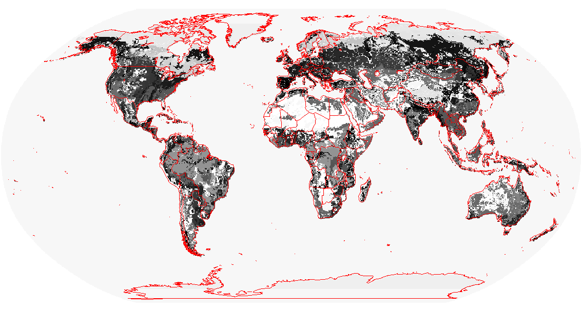
Figure 3.18: The USDA-NRCS map of the Keys to Soil Taxonomy soil suborders of the world at 20 km. The map shows the distribution of 12 soil orders. The original map also contains assumed distributions for suborders e.g. Histels, Udolls, Calcids, and similar. Projected in the Robinson projection commonly used to display world maps.
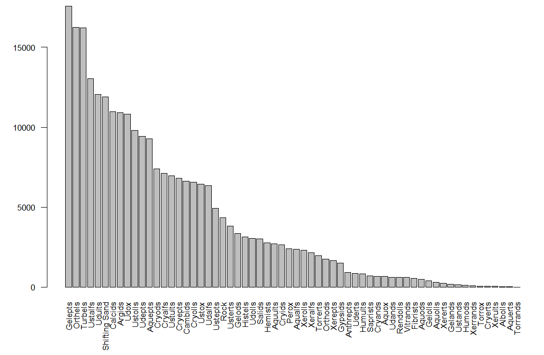
Figure 3.19: Distribution of the USDA suborders shown in Fig. 3.18.
Soil types can be mapped from field observations using statistically robust methods such as multinomial logistic regression as implemented in the nnet package for R (Venables and Ripley 2002). Theoretically, given a sufficient number and an adequate spatial distribution of field observed classes, multinomial logistic regression could even be used to map soil taxa at lower taxonomic levels with hundreds of unique taxonomic entities.
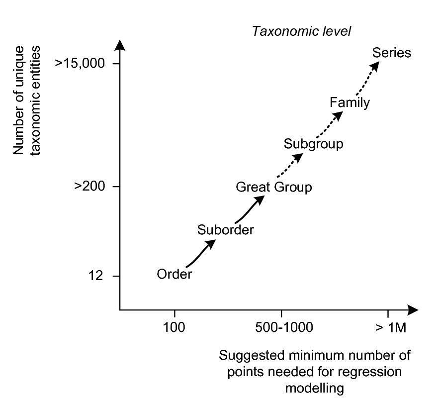
Figure 3.20: USDA classification system and approximate minimum number of observations required to fit a global multinomial regression model.
The map in Fig. 3.18 shows the global distribution of Soil Taxonomy soil suborders according to USDA-NRCS World Soil Index. Assuming a rule of thumb that we need at least 5 and, if possible, 10 observations of a specific soil taxonomic entity per unique combination of predictor variables and observations (Harrell 2001), it is possible to estimate that the optimum number of field observations required to e.g. predict the global distribution of USDA soil series would be in the order of few millions of classified soil profiles (Fig. 3.20).
3.6.2 Other factor-type variables
Pedometric / geostatistical methods can be used not only to predict the spatial distribution of soil types but also of any other categorical soil variables. There are many soil categorical variables for which maps would be extremely useful for soil management and modelling. We list here some of the most well known / most widely used soil categorical variables:
Diagnostic soil horizons — Diagnostic soil horizons (e.g. Mollic or Gypsic horizon in the WRB system) are soil layers with specific soil properties commonly developed as a result of soil formation processes. They are much easier to detect in the field than soil types but are rarely mapped over entire areas. Diagnostic soil horizons can theoretically be mapped as 3D soil polygons or probabilities (rasters) attached to specific depths.
Soil material classes — Soil horizons or whole profiles can be dominated by minerals or their combinations e.g. organic material in the soil, calcaric material, tephric material etc.
Munsell colour classes — Soil in dry and/or wet condition can be described using some 1–2 thousand Munsell colour classes. Each Munsell colour class carries a lot of information about the soil (Fernandez et al. 1988), so that a map of Munsell soil colour classes could be very useful for soil management.
Soil management zones — Each unique combination of soil properties or types and management zones can be further expanded into a mixed classification system.
Land degradation classes — Land degradation classes contain information about soil, but also about land cover and land use.
As with any map, categorical, factor-type soil variables can be mapped globally (together with the uncertainty) as long as there is sufficient training field data to properly support application of the prediction algorithm. The other technical problem is the amount of storage required to save and share all the produced predictions. Each category of a soil categorical variable must be mapped separately, which can lead to hundreds of grids. The global land cover map for example contains only some 35 categories, so that it is relatively easy to distribute and use it inside a GIS.
3.7 Importing and formatting soil data in R
3.7.1 Converting texture-by-hand classes to fractions
In the following example we look at how to convert texture-by-hand estimated classes to texture fractions i.e. sand, silt and clay content in %. We focus on the USDA texture-by-hand classes, which are embedded in the soiltexture package, kindly contributed by Julien Moeys. The USDA texture triangle can be accessed by:
library(soiltexture)
#> Warning: no DISPLAY variable so Tk is not available
TT.plot(class.sys = "USDA.TT")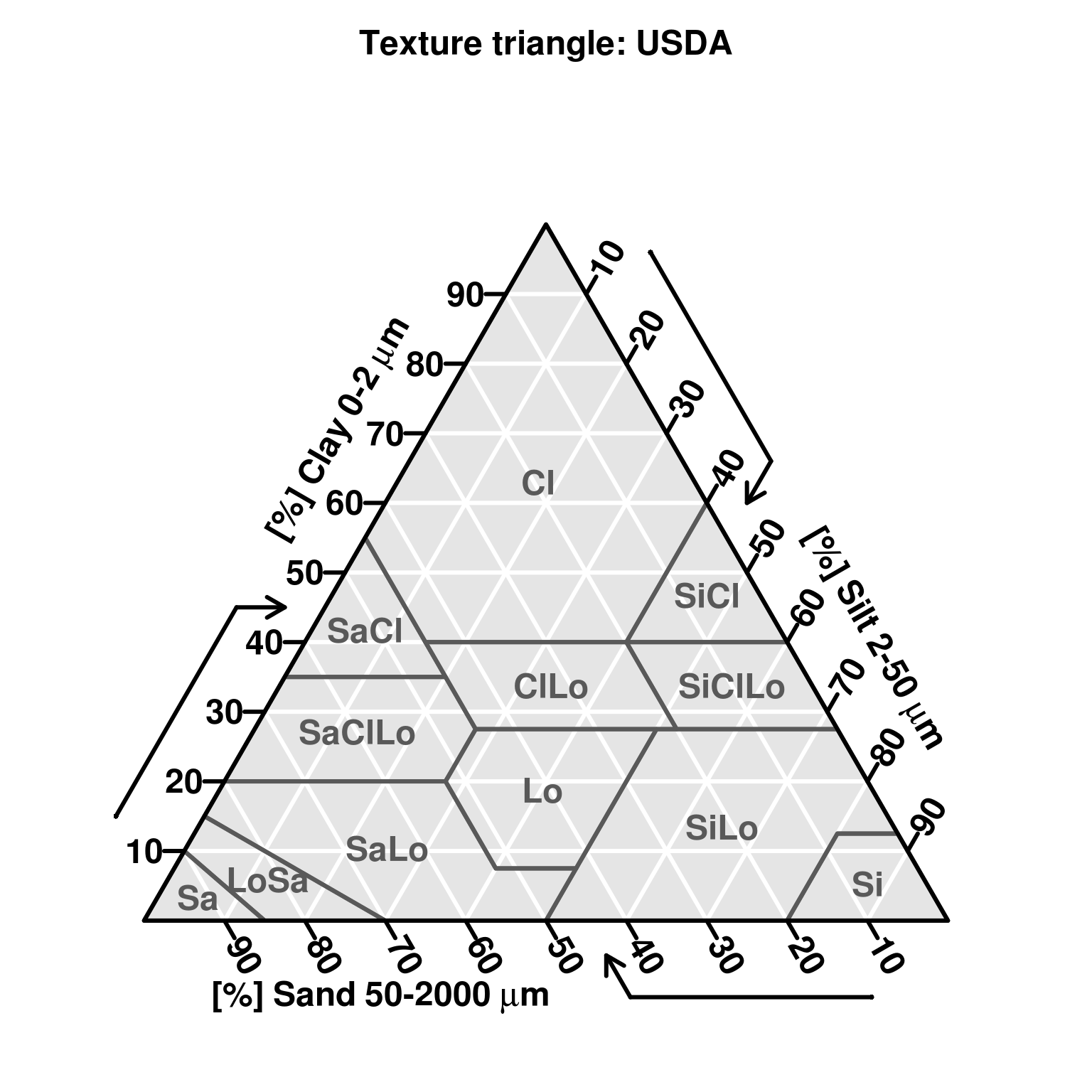
Figure 3.21: Soil texture triangle based on the USDA system. Generated using the soiltexture package (http://cran.r-project.org/web/packages/soiltexture/).
We can also print out a table with all class names and vertices numbers that defines each class:
TT.classes.tbl(class.sys="USDA.TT", collapse=", ")
#>       abbr     name              points
#>  [1,] "Cl"     "clay"            "24, 1, 5, 6, 2"
#>  [2,] "SiCl"   "silty clay"      "2, 6, 7"
#>  [3,] "SaCl"   "sandy clay"      "1, 3, 4, 5"
#>  [4,] "ClLo"   "clay loam"       "5, 4, 10, 11, 12, 6"
#>  [5,] "SiClLo" "silty clay loam" "6, 12, 13, 7"
#>  [6,] "SaClLo" "sandy clay loam" "3, 8, 9, 10, 4"
#>  [7,] "Lo"     "loam"            "10, 9, 16, 17, 11"
#>  [8,] "SiLo"   "silty loam"      "11, 17, 22, 23, 18, 19, 13, 12"
#>  [9,] "SaLo"   "sandy loam"      "8, 14, 21, 22, 17, 16, 9"
#> [10,] "Si"     "silt"            "18, 23, 26, 19"
#> [11,] "LoSa"   "loamy sand"      "14, 15, 20, 21"
#> [12,] "Sa"     "sand"            "15, 25, 20"
So knowing that the soil texture classes are defined geometrically, a logical estimate of the texture fractions from a class is to take the geometric centre of each polygon in the texture triangle. To estimate where the geometric centre is, we can for example use the functionality in the sp package. We start by creating a SpatialPolygons object, for which we have to calculate coordinates in the xy space and bind polygons one by one:
vert <- TT.vertices.tbl(class.sys = "USDA.TT")
vert$x <- 1-vert$SAND+(vert$SAND-(1-vert$SILT))*0.5
vert$y <- vert$CLAY*sin(pi/3)
USDA.TT <- data.frame(TT.classes.tbl(class.sys = "USDA.TT", collapse = ", "))
TT.pnt <- as.list(rep(NA, length(USDA.TT$name)))
poly.lst <- as.list(rep(NA, length(USDA.TT$name)))
next we strip the vertices and create a list of polygons:
library(sp)
for(i in 1:length(USDA.TT$name)){
  TT.pnt[[i]] <- as.integer(strsplit(unclass(paste(USDA.TT[i, "points"])), ", ")[[1]])
  poly.lst[[i]] <- vert[TT.pnt[[i]],c("x","y")]
  ## add extra point:
  pp <- Polygon(rbind(poly.lst[[i]], poly.lst[[i]][1,]))
  poly.lst[[i]] <- sp::Polygons(list(pp), ID=i)
}
and convert texture triangle to a spatial object:
poly.sp <- SpatialPolygons(poly.lst, proj4string=CRS(as.character(NA)))
poly.USDA.TT <- SpatialPolygonsDataFrame(poly.sp,
                      data.frame(ID=USDA.TT$name), match.ID=FALSE)
The resulting object now also contains slots of type labpt which is exactly the geometric gravity point of the first polygon automatically derived by the SpatialPolygons function.
slot(slot(poly.USDA.TT, "polygons")[[1]], "labpt")
#> [1] 0.490 0.545
Next we need to create a function that converts the xy coordinates (columns) in a texture triangle to texture fraction values. Let’s call this function get.TF.from.XY:
get.TF.from.XY <- function(df, xcoord, ycoord) {
  df$CLAY <- df[,ycoord]/sin(pi/3)
  df$SAND <- (2 - df$CLAY - 2 * df[,xcoord]) * 0.5
  df$SILT <- 1 - (df$SAND + df$CLAY)
  return(df)
}
Now everything is ready to estimate the soil fractions based on a system of classes. For the case of the USDA classifications system we get:
USDA.TT.cnt <- data.frame(t(sapply(slot(poly.USDA.TT, "polygons"), slot, "labpt")))
USDA.TT.cnt$name <- poly.USDA.TT$ID
USDA.TT.cnt <- get.TF.from.XY(USDA.TT.cnt, "X1", "X2")
USDA.TT.cnt[,c("SAND","SILT","CLAY")] <- signif(USDA.TT.cnt[,c("SAND","SILT","CLAY")], 2)
USDA.TT.cnt[,c("name","SAND","SILT","CLAY")]
#>               name  SAND  SILT  CLAY
#> 1             clay 0.200 0.180 0.630
#> 2       silty clay 0.067 0.470 0.470
#> 3       sandy clay 0.520 0.067 0.420
#> 4        clay loam 0.320 0.340 0.340
#> 5  silty clay loam 0.100 0.560 0.340
#> 6  sandy clay loam 0.600 0.130 0.270
#> 7             loam 0.410 0.400 0.190
#> 8       silty loam 0.210 0.650 0.130
#> 9       sandy loam 0.650 0.250 0.100
#> 10            silt 0.073 0.870 0.053
#> 11      loamy sand 0.820 0.120 0.058
#> 12            sand 0.920 0.050 0.033
Now that we have created a function that converts values in the texture triangle to texture fractions, we can go further and even estimate the uncertainty of estimating each texture fraction based on the class. For this we can use simulations i.e. randomly sample 100 points within some texture class and then derive standard deviations for each texture fraction. Note that, although this sounds like a complicated operation, we can run this in two lines of code. For example to estimate uncertainty of converting the class Cl (clay) to texture fractions we can simulate 100 random points the class polygon using the spsample function from the sp package (Bivand, Pebesma, and Rubio 2013):
sim.Cl <- data.frame(spsample(poly.USDA.TT[poly.USDA.TT$ID=="clay",],
                              type="random", n=100))
sim.Cl <- get.TF.from.XY(sim.Cl, "x", "y")
sd(sim.Cl$SAND); sd(sim.Cl$SILT); sd(sim.Cl$CLAY)
#> [1] 0.123
#> [1] 0.113
#> [1] 0.142
which means that we should not expect better precision of estimating the clay content based on class Cl than ±15%.
For some real soil profile data set we could also plot all texture fractions in the texture triangle to see how frequently one should expect some soil classes to appear:
require(GSIF)
data(afsp)
tdf <- afsp$horizons[,c("CLYPPT", "SLTPPT", "SNDPPT")]
tdf <- tdf[!is.na(tdf$SNDPPT)&!is.na(tdf$SLTPPT)&!is.na(tdf$CLYPPT),]
tdf <- tdf[runif(nrow(tdf))<.15,]
tdf$Sum <- rowSums(tdf)
for(i in c("CLYPPT", "SLTPPT", "SNDPPT")) { tdf[,i] <- tdf[,i]/tdf$Sum * 100 }
names(tdf)[1:3] <- c("CLAY", "SILT", "SAND")TT.plot(class.sys = "USDA.TT", tri.data = tdf,
grid.show = FALSE, pch="+", cex=.4, col="red")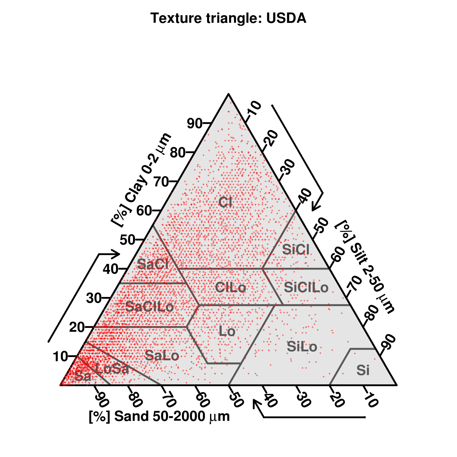
Figure 3.22: Distribution of observed soil textures for the Africa Soil Profiles.
This shows that not all positions in the triangle have the same prior probability. So probably a more sensitive way to estimate uncertainty of converting soil texture classes to fractions would be to run simulations using a density image showing the actual distribution of classes and then, by using the rpoint function in the spatstat package, we could also derive even more realistic conversions from texture-by-hand classes to texture fractions.
3.7.2 Converting Munsell color codes to other color systems
In the next example we look at the Munsell color codes and conversion algorithms from a code to RGB and other color spaces. Munsell color codes can be matched with RGB values via the Munsell color codes conversion table. You can load a table with 2350 entries from the book repository:
load("extdata/munsell_rgb.rdata")
library(colorspace)
munsell.rgb[round(runif(1)*2350, 0),]
#>       Munsell  R  G  B
#> 2254 7.5Y_1_2 37 34 17as(colorspace::RGB(R=munsell.rgb[1007,"R"]/255,
G=munsell.rgb[1007,"G"]/255,
B=munsell.rgb[1007,"B"]/255), "HSV")
#> H S V
#> [1,] 3.53 0.0798 0.835This shows that, for any given Munsell color code, it is relatively easy to convert it to any other color system available in R.
Within the R package aqp one can directly transform Munsell color codes to standard color classes in R (Beaudette, Roudier, and O’Geen 2013). For example, to convert the Munsell color code to RGB values from the example above we would run:
aqp::munsell2rgb(the_hue = "10B", the_value = 2, the_chroma = 12)
#> [1] "#003A7CFF"
Now the colors are coded in the hexadecimal format, which is quite abstract but can be easily browsed via some web color table. To get the actual RGB values we would run:
grDevices::col2rgb("#003A7CFF")
#>       [,1]
#> red      0
#> green   58
#> blue   124
The hex triplet format is also very similar to the color format used in the KML reference:
plotKML::col2kml("#003A7CFF")
#> [1] "#ff7c3a00"
To plot the actual colors based on an actual soil profile database we often need to prepare the color codes before we can run the conversion (Rossel et al. 2006). In the case of the Africa Soil Profile Database:
data(afsp)
head(afsp$horizons[!is.na(afsp$horizons$MCOMNS),"MCOMNS"])
#> [1] 10YR3/3 10YR3/3 10YR3/3 10YR3/3 10YR3/3 10YR3/3
#> 289 Levels: 10BG4/1 10R2.5/1 10R2/1 10R2/2 10R3/2 10R3/3 10R3/4 ... N7/0
Note that the Munsell color codes have been prepared as text. Hence we need to spend some effort to separate hue from saturation and intensity before we can derive and plot actual colors. We start by merging the tables of interest so both coordinates and Munsell color codes are available in the same table:
mcol <- plyr::join(afsp$horizons[,c("SOURCEID","MCOMNS","UHDICM","LHDICM")],
                   afsp$sites[,c("SOURCEID","LONWGS84","LATWGS84")])
#> Joining by: SOURCEID
mcol <- mcol[!is.na(mcol$MCOMNS),]
str(mcol)
#> 'data.frame':    31502 obs. of  6 variables:
#>  $ SOURCEID: Factor w/ 26270 levels "100902","100903",..: 974 974 974 974 974 974 975 975 975 975 ...
#>  $ MCOMNS  : Factor w/ 289 levels "10BG4/1","10R2.5/1",..: 40 40 40 40 40 40 23 23 23 23 ...
#>  $ UHDICM  : num  0 8 25 50 81 133 0 8 19 30 ...
#>  $ LHDICM  : num  8 25 50 81 133 160 8 19 30 50 ...
#>  $ LONWGS84: num  17.6 17.6 17.6 17.6 17.6 ...
#>  $ LATWGS84: num  -11 -11 -11 -11 -11 ...
Next we need to format all Munsell color codes to Hue_Saturation_Intensity format. We can incrementally replace the existing codes until all codes can be matched with the RGB table:
mcol$Munsell <- sub(" ", "", sub("/", "_", mcol$MCOMNS))
hue.lst <- expand.grid(c("2.5", "5", "7.5", "10"),
                       c("YR","GY","BG","YE","YN","YY","R","Y","B","G"))
hue.lst$mhue <- paste(hue.lst$Var1, hue.lst$Var2, sep="")
for(j in hue.lst$mhue[1:28]){
  mcol$Munsell <- sub(j, paste(j, "_", sep=""), mcol$Munsell, fixed=TRUE)
}
mcol$depth <- mcol$UHDICM + (mcol$LHDICM-mcol$UHDICM)/2
mcol.RGB <- merge(mcol, munsell.rgb, by="Munsell")
str(mcol.RGB)
#> 'data.frame':    11806 obs. of  11 variables:
#>  $ Munsell : chr  "10R_2_2" "10R_2_2" "10R_2_2" "10R_2_2" ...
#>  $ SOURCEID: Factor w/ 26270 levels "100902","100903",..: 18724 18724 20331 18724 20331 20331 18724 9089 4859 23688 ...
#>  $ MCOMNS  : Factor w/ 289 levels "10BG4/1","10R2.5/1",..: 4 4 4 4 4 4 4 5 5 5 ...
#>  $ UHDICM  : num  90 35 30 10 53 0 0 18 0 0 ...
#>  $ LHDICM  : num  135 90 53 35 98 30 10 24 15 5 ...
#>  $ LONWGS84: num  32.23 32.23 4.76 32.23 4.76 ...
#>  $ LATWGS84: num  -26.15 -26.15 8.79 -26.15 8.79 ...
#>  $ depth   : num  112.5 62.5 41.5 22.5 75.5 ...
#>  $ R       : int  67 67 67 67 67 67 67 91 91 91 ...
#>  $ G       : int  48 48 48 48 48 48 48 68 68 68 ...
#>  $ B       : int  45 45 45 45 45 45 45 63 63 63 ...
Which allows us to plot the actual observed colors of the top soil (0–30 cm) for the whole of Africa:
mcol.RGB <- mcol.RGB[!is.na(mcol.RGB$R),]
mcol.RGB$Rc <- round(mcol.RGB$R/255, 3)
mcol.RGB$Gc <- round(mcol.RGB$G/255, 3)
mcol.RGB$Bc <- round(mcol.RGB$B/255, 3)
mcol.RGB$col <- rgb(mcol.RGB$Rc, mcol.RGB$Gc, mcol.RGB$Bc)
mcol.RGB <- mcol.RGB[mcol.RGB$depth>0 & mcol.RGB$depth<30 & !is.na(mcol.RGB$col),]
coordinates(mcol.RGB) <- ~ LONWGS84+LATWGS84load("extdata/admin.af.rda")
proj4string(admin.af) <- "+proj=longlat +datum=WGS84"
#> Warning in ReplProj4string(obj, CRS(value)): A new CRS was assigned to an object with an existing CRS:
#> +proj=longlat +datum=WGS84 +no_defs +ellps=WGS84 +towgs84=0,0,0
#> without reprojecting.
#> For reprojection, use function spTransform
country <- as(admin.af, "SpatialLines")
par(mar=c(.0,.0,.0,.0), mai=c(.0,.0,.0,.0))
plot(country, col="darkgrey", asp=1)
points(mcol.RGB, pch=21, bg=mcol.RGB$col, col="black")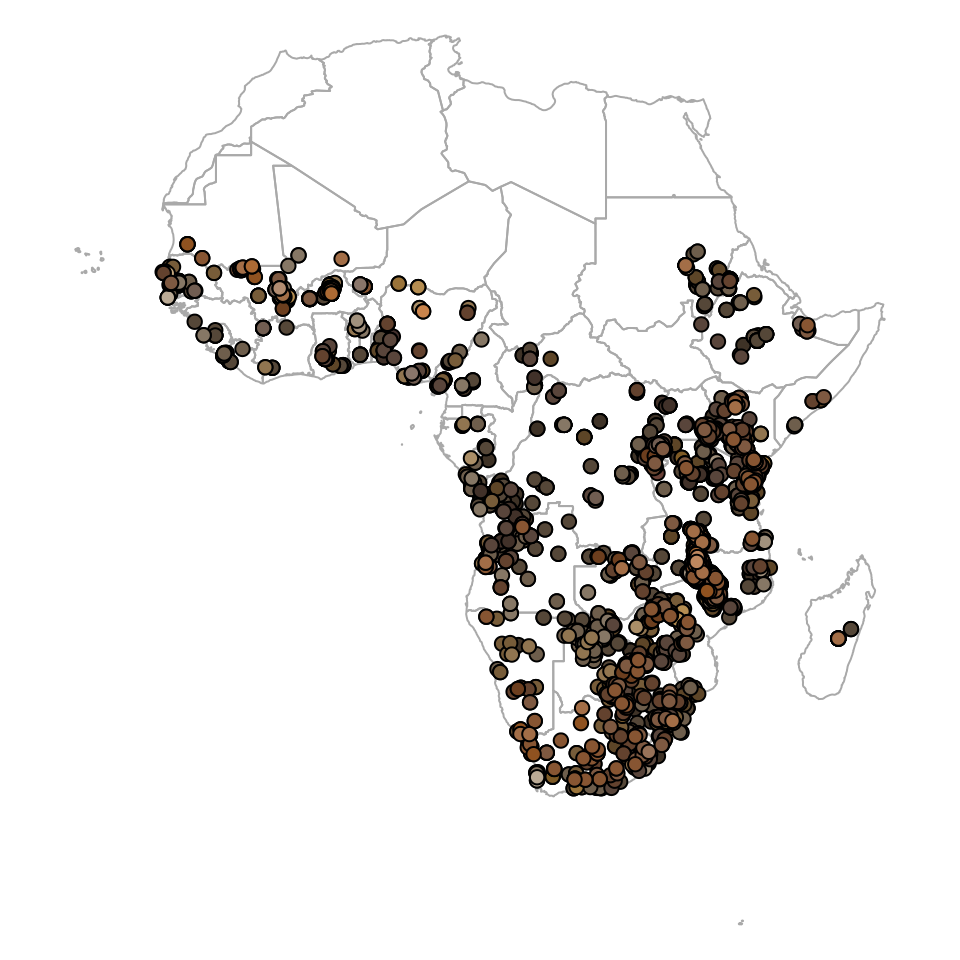
Figure 3.23: Actual observed soil colors (moist) for the top soil based on the Africa Soil Profiles Database.
Finally, via the plotKML package you can also plot the actual colors of horizons by converting tables to SoilProfileCollection class in the aqp package. Consider this soil profile from Nigeria:
library(plyr)
library(aqp)
#> This is aqp 1.17
#>
#> Attaching package: 'aqp'
#> The following object is masked from 'package:base':
#>
#>     union
lon = 3.90; lat = 7.50; id = "ISRIC:NG0017"; FAO1988 = "LXp"
top = c(0, 18, 36, 65, 87, 127)
bottom = c(18, 36, 65, 87, 127, 181)
ORCDRC = c(18.4, 4.4, 3.6, 3.6, 3.2, 1.2)
hue = c("7.5YR", "7.5YR", "2.5YR", "5YR", "5YR", "10YR")
value = c(3, 4, 5, 5, 5, 7); chroma = c(2, 4, 6, 8, 4, 3)
## prepare a SoilProfileCollection:
prof1 <- plyr::join(data.frame(id, top, bottom, ORCDRC, hue, value, chroma),
              data.frame(id, lon, lat, FAO1988), type='inner')
#> Joining by: id
prof1$soil_color <- with(prof1, aqp::munsell2rgb(hue, value, chroma))
#> Notice: converting hue to character
depths(prof1) <- id ~ top + bottom
#> Warning: converting IDs from factor to character
site(prof1) <- ~ lon + lat + FAO1988
coordinates(prof1) <- ~ lon + lat
proj4string(prof1) <- CRS("+proj=longlat +datum=WGS84")
prof1
#> Object of class SoilProfileCollection
#> Number of profiles: 1
#>
#> Horizon attributes:
#>             id top bottom ORCDRC   hue value chroma soil_color hzID
#> 1 ISRIC:NG0017   0     18   18.4 7.5YR     3      2  #584537FF    1
#> 2 ISRIC:NG0017  18     36    4.4 7.5YR     4      4  #7E5A3BFF    2
#> 3 ISRIC:NG0017  36     65    3.6 2.5YR     5      6  #A96C4FFF    3
#> 4 ISRIC:NG0017  65     87    3.6   5YR     5      8  #B06A32FF    4
#> 5 ISRIC:NG0017  87    127    3.2   5YR     5      4  #9A7359FF    5
#> 6 ISRIC:NG0017 127    181    1.2  10YR     7      3  #C4AC8CFF    6
#>
#> Sampling site attributes:
#>             id FAO1988
#> 1 ISRIC:NG0017     LXp
#>
#> Spatial Data:
#>     min max
#> lon 3.9 3.9
#> lat 7.5 7.5
#> [1] "+proj=longlat +datum=WGS84 +ellps=WGS84 +towgs84=0,0,0"
Once an object is in the format of SoilProfileCollection it can be directly plotted in Google Earth via the generic plotKML command:
plotKML(prof1, var.name="ORCDRC", color.name="soil_color")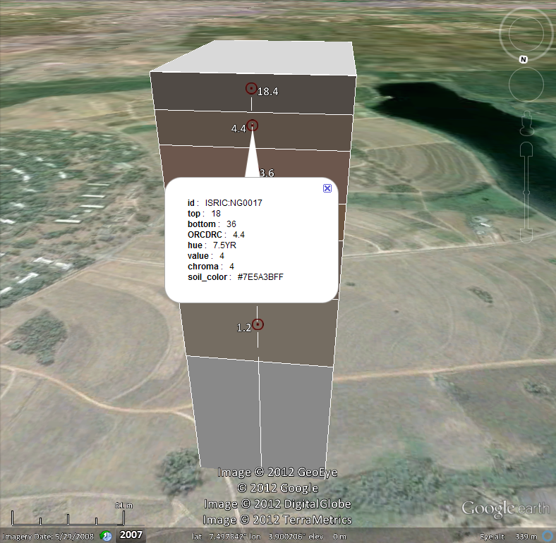
Figure 3.24: Soil profile from Nigeria plotted in Google Earth with actual observed colors.
3.8 Using Machine Learning to build Pedo-Transfer-Functions
3.8.1 PTF for Bulk Density
In the following examples we look at possibilities of using Machine Learning to predict soil properties and classes from other soil properties and classes. In the first example, we try to build a Pedo-Transfer-Function (PTF) to predict bulk density using soil properties such as organic carbon content, soil texture and coarse fragments. Bulk density is often only available for a part of soil profiles, so if we could use a PTF to fill in all gaps in bulk density, then most likely we would not need to omit BD from further analysis. For testing PTFs to predict bulk density from other soil properties we will use a subset of the ISRIC WISE soil profile data set (Batjes 2009), which can be loaded from:
library(randomForestSRC)
#>
#>  randomForestSRC 2.8.0
#>
#>  Type rfsrc.news() to see new features, changes, and bug fixes.
#>
library(ggRandomForests)
#>
#> Attaching package: 'ggRandomForests'
#> The following object is masked from 'package:randomForestSRC':
#>
#>     partial.rfsrc
library(ggplot2)
library(scales)
load("extdata/sprops.wise.rda")
str(SPROPS.WISE)
#> 'data.frame':    47833 obs. of  17 variables:
#>  $ SOURCEID: Factor w/ 10253 levels "AF0001","AF0002",..: 1 1 1 2 2 2 2 3 3 3 ...
#>  $ SAMPLEID: chr  "AF0001_1" "AF0001_2" "AF0001_3" "AF0002_1" ...
#>  $ UHDICM  : int  0 15 60 0 20 60 110 0 20 50 ...
#>  $ LHDICM  : int  15 60 150 20 60 110 170 20 50 110 ...
#>  $ DEPTH   : num  7.5 37.5 105 10 40 85 140 10 35 80 ...
#>  $ CRFVOL  : int  20 NA NA NA NA NA NA NA NA NA ...
#>  $ CECSUM  : num  NA NA NA NA NA NA NA NA NA NA ...
#>  $ SNDPPT  : int  40 10 10 40 15 10 40 40 65 60 ...
#>  $ CLYPPT  : int  20 35 35 20 20 35 20 20 10 25 ...
#>  $ BLD     : num  NA NA NA NA NA NA NA NA NA NA ...
#>  $ SLTPPT  : int  40 55 55 40 65 55 40 40 25 15 ...
#>  $ PHIHOX  : num  7.9 7.9 7.9 8.5 8.6 8.5 8.8 8.8 9.2 8.9 ...
#>  $ PHIKCL  : num  NA NA NA NA NA NA NA NA NA NA ...
#>  $ ORCDRC  : num  7.6 2.3 0.9 12.8 6 3.9 2.7 5.9 2.4 NA ...
#>  $ LONWGS84: num  69.2 69.2 69.2 69.2 69.2 ...
#>  $ LATWGS84: num  34.5 34.5 34.5 34.5 34.5 34.5 34.5 34.5 34.5 34.5 ...
#>  $ SOURCEDB: chr  "WISE" "WISE" "WISE" "WISE" ...
For model fitting we will use the randomForestSRC package, which is a robust implementation of the random forest algorithm with options for parallelization and visualization of model outputs:
bd.fm = as.formula("BLD ~ ORCDRC + PHIHOX + SNDPPT + CLYPPT + CRFVOL + DEPTH")
rfsrc_BD <- rfsrc(bd.fm, data=SPROPS.WISE)
rfsrc_BD
#>                          Sample size: 3330
#>                      Number of trees: 1000
#>            Forest terminal node size: 5
#>        Average no. of terminal nodes: 685
#> No. of variables tried at each split: 2
#>               Total no. of variables: 6
#>        Resampling used to grow trees: swr
#>     Resample size used to grow trees: 3330
#>                             Analysis: RF-R
#>                               Family: regr
#>                       Splitting rule: mse *random*
#>        Number of random split points: 10
#>                 % variance explained: 39.6
#>                           Error rate: 46370
which shows that the model explains about 40% with an RMSE of ±200 kg/m\(^3\). Although the MSE is relatively high, the model can at least be used to fill-in the missing values for BD. We can plot the partial plots between the target variable and all covariates by using:
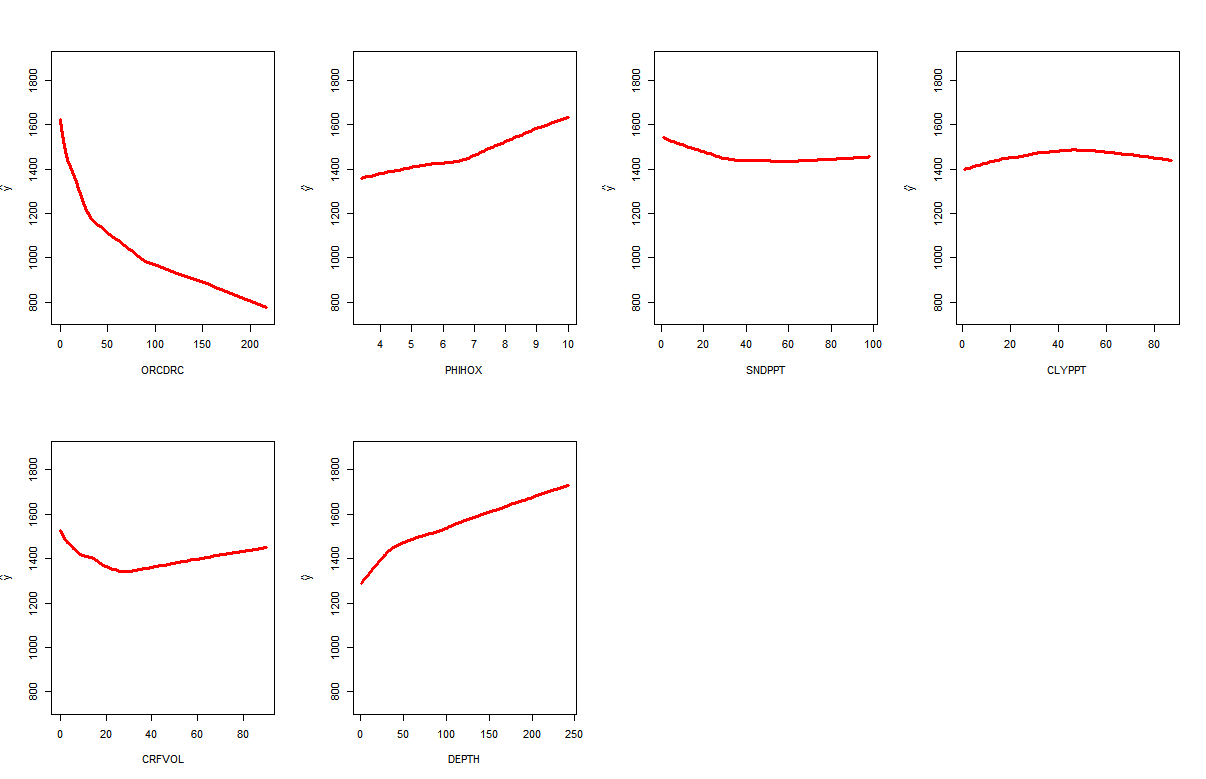
Figure 3.25: Bulk density as a function of organic carbon, pH, sand and clay content, coarse fragments and depth.
Obviously, the key to explaining bulk density is soil organic carbon, while depth and pH are the 2nd and 3rd most important covariates. Using this MLA-based model we can predict bulk density for various combinations of soil properties:
predict(rfsrc_BD, data.frame(ORCDRC=1.2, PHIHOX=7.6,
                  SNDPPT=45, CLYPPT=12, CRFVOL=0, DEPTH=20))$predicted
#> [1] 1548
and for a soil with higher organic carbon content:
predict(rfsrc_BD, data.frame(ORCDRC=150, PHIHOX=4.6,
                  SNDPPT=25, CLYPPT=35, CRFVOL=0, DEPTH=20))$predicted
#> [1] 906
3.8.2 PTF for correlating classification systems
In the second example we use ISRIC WISE data set to build a correlation function to translate soil classes from one classification system to the other. The training data can be loaded from:
load("extdata/wise_tax.rda")
str(WISE_tax)
#> 'data.frame':    8189 obs. of  7 variables:
#>  $ SOURCEID: Factor w/ 8189 levels "AF0001","AF0002",..: 1 2 3 4 5 6 7 8 9 10 ...
#>  $ LATWGS84: num  34.5 34.5 34.5 34.3 32.4 ...
#>  $ LONWGS84: num  69.2 69.2 69.2 61.4 62.1 ...
#>  $ TAXNWRB : Factor w/ 146 levels "#N/A","Albic Arenosol",..: 104 9 9 72 17 16 122 49 8 9 ...
#>  $ TAXOUSDA: Factor w/ 1728 levels ""," Calciorthid",..: 1 1 1 1 1 1 1 1 1 1 ...
#>  $ LFORM   : chr  "LV" "LV" "LV" "LV" ...
#>  $ LANDUS  : chr  "AA4" "AA6" "AA6" "AA4" ...
For this purpose we also need to import the cleaned legend for USDA classification:
leg <- read.csv("extdata/taxousda_greatgroups.csv")
str(leg)
#> 'data.frame':    434 obs. of  4 variables:
#>  $ Great_Group: Factor w/ 434 levels "Acraquox","Acrohumox",..: 9 57 77 112 121 145 170 259 286 301 ...
#>  $ Suborder   : Factor w/ 79 levels "Albolls","Andepts",..: 4 4 4 4 4 4 4 4 4 4 ...
#>  $ Order      : Factor w/ 12 levels "Alfisols","Andisols",..: 1 1 1 1 1 1 1 1 1 1 ...
#>  $ TAX        : Factor w/ 434 levels "Alfisols_Aqualfs_Albaqualfs",..: 1 2 3 4 5 6 7 8 9 10 ...
Our objective is to develop a function to translate WRB classes into USDA classes with help of some soil properties. We can try to add soil pH and clay content to increase the accuracy of the model:
x.PHIHOX <- aggregate(SPROPS.WISE$PHIHOX,
                      by=list(SPROPS.WISE$SOURCEID),
                      FUN=mean, na.rm=TRUE); names(x.PHIHOX)[1] = "SOURCEID"
x.CLYPPT <- aggregate(SPROPS.WISE$CLYPPT,
                      by=list(SPROPS.WISE$SOURCEID),
                      FUN=mean, na.rm=TRUE); names(x.CLYPPT)[1] = "SOURCEID"
WISE_tax$PHIHOX <- plyr::join(WISE_tax, x.PHIHOX, type="left")$x
#> Joining by: SOURCEID
WISE_tax$CLYPPT <- plyr::join(WISE_tax, x.CLYPPT, type="left")$x
#> Joining by: SOURCEID
After that we need to clean-up the classes so that we can focus on USDA suborders only:
sel.tax = complete.cases(WISE_tax[,c("TAXNWRB","PHIHOX","CLYPPT","TAXOUSDA")])
WISE_tax.sites <- WISE_tax[sel.tax,]
WISE_tax.sites$TAXOUSDA.f <- NA
for(j in leg$Suborder){
  sel <- grep(j, WISE_tax.sites$TAXOUSDA, ignore.case=TRUE)
  WISE_tax.sites$TAXOUSDA.f[sel] = j
}
WISE_tax.sites$TAXOUSDA.f <- as.factor(WISE_tax.sites$TAXOUSDA.f)
WISE_tax.sites$TAXNWRB <- as.factor(paste(WISE_tax.sites$TAXNWRB))
and finally we can fit a model to translate WRB profiles to USDA suborders:
TAXNUSDA.rf <- rfsrc(TAXOUSDA.f ~ TAXNWRB + PHIHOX + CLYPPT, data=WISE_tax.sites)
#TAXNUSDA.rf
This shows that the average accuracy is about 45%. We can test converting some classes with the help of additional soil properties:
newdata = data.frame(TAXNWRB=factor("Calcaric Cambisol",
                  levels=levels(WISE_tax.sites$TAXNWRB)),
                  PHIHOX=7.8, CLYPPT=12)
x <- data.frame(predict(TAXNUSDA.rf, newdata, type="prob")$predicted)
x[,order(1/x)[1:2]]
#>   Ochrepts Orthids
#> 1    0.288   0.154
So for example, the two most likely classes to equate to Calcaric Cambisols seem to be Ochrepts and Orthids, which is not that much different from correlation classes reported in Krasilnikov et al. (2009).
3.9 Summary points
In this chapter, we have endeavoured to provide precise and explicit descriptions of the soil properties and soil classes of greatest interest to current PSM activities. For each soil property (or class) we have provided an explanation for why that property (or class) is of interest to users and why it has been selected to be mapped globally, by us and by others. In many cases, the most obvious reason is that the soil property is widely recorded and reported in legacy soil profile data bases and is therefore available. But these soil properties are widely reported for good reasons, mainly because they have been found to be important to consider when managing land or making decisions about land capability or use. We have defined the spatial attributes of the soil properties mapped at various scales, defined a standard reference (analysis) method for each soil property, provided information on the units, precision and range of values used to describe each mapped soil property and reviewed problems and opportunities related to harmonization of soil property values contained in legacy soil profile databases that have been analysed using different methods of analysis.
It should be noted that, in this chapter, we have emphasized the use of existing, or legacy, soil profile data to provide the evidence used to construct predicton models for PSM. This emphasis reflects the reality that, for most of the world, legacy soil profile data is all that we have to work with, at the present time, and all that we can reasonably expect in the foreseeable future. Many of the issues and challenges related to use and harmonization of legacy soil profile data discussed in this chapter will hopefully be of less importance as newer, contemporary data are collected in the field and analysed in the laboratory using more robust, statistically valid and reproduceable methods (e.g. spectroscopy). In the meantime, standardization and harmonization of legacy soil profile data will continue to present a challenge for global to regional PSM.
One attractive option for harmonizing soil analytical data following the SINFER concept would be to create and maintain a Global Soil Reference Library (GSRL). This concept is further discussed in the final chapter. Such a library would need to include data for a significant number of soils from each continent or region. Each soil would be analysed for all properties of interest using all commonly used methods of analysis. Values for a soil property for any soil analysed by a given method could be converted into equivalent values in any other analytical method (as long as data analysed by both methods were included in the GSRL) by developing pedo-transfer (or conversion) functions using the fully analysed samples in the conversion library. In particular, some variation of the similarity approach described by Jagtap et al. (2004) for available water capacity and Nemes et al. (1999) for harmonization of particle size data could be implemented to harmonize all types of soil property values anywhere in the world. The value of the soil property in the desired reference method could be estimated by finding the soil or soils in the reference library that were most similar to the soil for which harmonization was required and then using the value of the soil (or soils) in the desired reference method as the predicted harmonized value. If several similar soils were identified, as is done by Nemes et al. (1999), then the predicted harmonized value would be computed as a weighted mean, in the appropriate reference method, of all similar soils; with weights selected according to the similarity of the soils in the conversion library to the soil being harmonized.
What a GSRL would do, in effect, is to provide a single, centralized framework for harmonization and conversion of soil property values. It would do this using a database of reference soils analysed for all soil properties of interest by all major analytical methods. These fully analysed reference soils would provide a framework for computing individualized, locally relevant conversion or pedo-transfer functions in a consistent and standardized manner. Consequently, global soil mapping would benefit from having the best of both worlds, namely locally-specific harmonization functions (which are known to be most effective), and also ones that were computed in a single standardized manner using data in a single comprehensive reference database (which is desirable in terms of simplifying harmonization and maintaining a record of how any value was harmonized).
Over time, we expect to see progress made in developing, applying and documenting harmonization methods so that the values for any given soil property used to create predictive models for global soil property mapping are fully harmonized and roughly equivalent for all input data sets. In the shorter term, it is likely that the accuracy of global predictions will be reduced because of weak, inconsistent or completely absent efforts to harmonize soil property values produced using different analytical methods. In the longer term, we hope, and expect, that data collected in the future, as we move forward, will benefit from adoption of methods of data collection and analysis that are more systematic, more reproduceable, more accurate and more interchangeable. These improvements should reduce the need for harmonization and standardization and should make use of soil observation and measurement data easier and more consistent.
References
Arrouays, D., N. McKenzie, A.R. de Forges, J. Hempel, and A.B. McBratney. 2014. GlobalSoilMap: basis of the global spatial soil information system. Boca Raton, USA: CRC press.
Shepherd, K.D., and M.G. Walsh. 2007. “Infrared Spectroscopy — Enabling an Evidence Based Diagnostic Survellance Approach to Agricultural and Environmental Management in Developing Countries.” Journal of Near Infrared Spectroscopy 15:1–19.
Viscarra Rossel, Raphael A., Alex B. McBratney, and Budiman Minasny, eds. 2010. Proximal Soil Sensing. Progress in Soil Science. Springer.
Natural Resources Conservation Service. 2004. Soil Survey Laboratory Methods Manual Version 4.0. Edited by Rebecca Burt. Soil Survey Investigations Report No. 42. United States Department of Agriculture.
Carter, M.R., and E.G. Gregorich. 2007. Soil Sampling and Methods of Analysis. CRC PRESS.
Food, and Agriculture Organization of the United Nations. 2006. Guidelines for Soil Description. Food; Agriculture Organization of the United Nations.
Van Reeuwijk, L.P., ed. 2002. Procedures for Soil Analysis. Technical Paper 9. Wageningen, the Netherlands: ISRIC - World Soil Information.
Burrough, P. A., P.H. T. Beckett, and M.G. Jarvis. 1971. “The Relation Between Cost and Utility in Soil Survey (I–Iii).” Journal of Soil Science 22 (3). Blackwell Publishing Ltd:359–94. https://doi.org/10.1111/j.1365-2389.1971.tb01624.x.
Gehl, RonaldJ., and CharlesW. Rice. 2007. “Emerging Technologies for in Situ Measurement of Soil Carbon.” Climatic Change 80 (1-2). Kluwer Academic Publishers:43–54. https://doi.org/10.1007/s10584-006-9150-2.
Kempen, B. 2011. “Updating Soil Information with Digital Soil Mapping.” PhD thesis, Wageningen: Wageningen University. http://edepot.wur.nl/187198.
Bouma, J., N. H. Batjes, and J. J. R. Groot. 1998. “Exploring Land Quality Effects on World Food Supply.” Geoderma 86 (1). Elsevier:43–59.
FAO. 1990. Guidelines for Soil Profile Description. 3rd ed. Rome: Food; Agriculture Organization of the United Nations.
Soil survey Division staff. 1993. Soil Survey Manual. Vol. Handbook 18. Washington: United States Department of Agriculture.
Harpstead, M.I., T.J. Sauer, and W.F. Bennett. 2001. Soil Science Simplified. Wiley.
Burrough, P. A. 1989. “Fuzzy Mathematical Methods for Soil Survey and Land Evaluation.” Journal of Soil Science 40 (3):477–92. https://doi.org/10.1111/j.1365-2389.1989.tb01290.x.
de Gruijter, J. J., D. J. J. Walvoort, and P. F. M. van Gaans. 1997. “Continuous Soil Maps — a Fuzzy Set Approach to Bridge the Gap Between Aggregation Levels of Process and Distribution Models.” Geoderma 77 (2-4):169–95.
Van Engelen, V.W.P., and J.A. Dijkshoorn, eds. 2012. Global and National Soils and Terrain Digital Databases (SOTER), Procedures Manual, version 2.0. ISRIC Report 2012/04. Wageningen, the Netherlands: ISRIC - World Soil Information.
FAO/IIASA/ISRIC/ISS-CAS/JRC. 2012. Harmonized World Soil Database (Version 1.2). Rome: FAO.
Arrouays, Dominique, Michael G. Grundy, Alfred E. Hartemink, Jonathan W. Hempel, Gerard B.M. Heuvelink, S. Young Hong, Philippe Lagacherie, et al. 2014. “Chapter Three — GlobalSoilMap: Toward a Fine-Resolution Global Grid of Soil Properties.” In Soil Carbon, edited by Donald L. Sparks, 125:93–134. Advances in Agronomy. Academic Press. https://doi.org/10.1016/B978-0-12-800137-0.00003-0.
Sleutel, S., S. De Neve, B. Singier, and G. Hofman. 2007. “Quantification of Organic Carbon in Soils: A Comparison of Methodologies and Assessment of the Carbon Content of Organic Matter.” Communications in Soil Science and Plant Analysis 38:2647–57.
Batjes, Niels, Eloi Ribeiro, Ad van Oostrum, Johan G.B. Leenaars, Tomislav Hengl, and Jorge Mendes de Jesus. 2017. “WoSIS: Providing standardised soil profile data for the world.” Earth System Science Data 9 (January):1–14.
Richter, Daniel D., and Daniel Markewitz. 1995. “How Deep Is Soil?” BioScience 45 (9). University of California Press on behalf of the American Institute of Biological Sciences:600–609. http://www.jstor.org/stable/1312764.
Wilson, Tim. 2008. “OGC KML.” OGC Standard OGC 07-147r2. Open Geospatial Consortium Inc.
FAO. 2006. Guidelines for Soil Profile Description. 4th ed. Rome: Food; Agriculture Organization of the United Nations.
Rijsberman, Frank R, and M Gordon Wolman. 1985. “Effect of Erosion on Soil Productivity: An International Comparison.” Journal of Soil and Water Conservation 40 (4). Soil; Water Conservation Society:349–54.
Driessen, Paul M, and Nicolaas T Konijn. 1992. Land-Use Systems Analysis. Wageningen Agricultural University.
Leenaars, Johan G.B. 2014. Africa Soil Profiles Database, Version 1.2. A Compilation of Geo-Referenced and Standardized Legacy Soil Profile Data for Sub Saharan Africa (with Dataset). Wageningen, the Netherlands: Africa Soil Information Service (AfSIS) project; ISRIC — World Soil Information.
Smith, P., P. Falloon, and L. Kutsch. 2004. “Soils as Carbon Sinks: The Global Context.” Soil Use and Management 20 (2). Blackwell Publishing Ltd:212–18. https://doi.org/10.1111/j.1475-2743.2004.tb00361.x.
Pete Smith, Pete Falloon, and Werner L. Kutsch. 2010. “The role of soils in the Kyoto Protocol.” In Soil Carbon Dynamics, edited by M. Bahn, 245–56. Cambridge University Press. https://doi.org/10.1017/CBO9780511711794.014.
Panagos, Panos, Roland Hiederer, Marc Van Liedekerke, and Francesca Bampa. 2013. “Estimating soil organic carbon in Europe based on data collected through an European network.” Ecological Indicators 24 (0):439–50. https://doi.org/10.1016/j.ecolind.2012.07.020.
Conant, Richard T, Stephen M Ogle, Eldor A Paul, and Keith Paustian. 2010. “Measuring and Monitoring Soil Organic Carbon Stocks in Agricultural Lands for Climate Mitigation.” Frontiers in Ecology and the Environment 9 (3). Ecological Society of America:169–73. http://dx.doi.org/10.1890/090153.
Scharlemann, Jörn P. W., Edmund V. J. Tanner, Roland Hiederer, and Valerie Kapos. 2014. “Global Soil Carbon: Understanding and Managing the Largest Terrestrial Carbon Pool.” Carbon Management 5 (1). Future Science:81–91. https://doi.org/10.4155/cmt.13.77.
Grewal, K.S., G.D. Buchan, and R.R. Sherlock. 1991. “A comparison of three methods of organic carbon determination in some New Zealand soils.” Journal of Soil Science 42:251–57.
Meersmans, J., B. Van Wesemael, and M. Van Molle. 2009. “Determining soil organic carbon for a agricultural soils: A comparison between the Walkley & Black and the dry combustion methods (north Belgium).” Soil Use and Management 25:346–53.
Bisutti, I., I. Hilke, and M. Raessler. 2004. “Determination of total organic carbon — an overview of current methods.” Trends in Analytical Chemistry 23 (10-11):716–26.
Kalembasa, S.J., and D.S. Jenkinson. 1973. “A Comparative Study of Titrimetric and Gravimetric Methods for the Determination of Organic Carbon in Soil.” Journal of the Science of Food and Agriculture 24:1085–90.
Soon, Y.K., and S. Abboud. 1991. “A comparison of some methods for soil organic carbon determination.” Communications in Soil Science and Plant Analysis 22:943–54.
Wang, X.J., P.J. Smethurst, and A.M. Herbed. 1996. “Relationships between three measures of organic matter or carbon in soils of eucalypt plantations in Tasmania.” Australian Journal of Soil Research 34:545–53.
Konen, M.E., P.M. Jacobs, C.L. Burras, B.J. Talaga, and J.A. Mason. 2002. “Equations for Predicting Soil Organic Carbon Using Loss-on-Ignitionfor North Central U.S. Soils.” Soil Science Society of America Journal 66:1878–81.
Brye, K.R., and N.A. Slaton. 2003. “Carbon and Nitrogen Storage in a Typic Albaqualf as Affected by Assessment Method.” Communications in Soil Science and Plant Analysis 34:1637–55.
Mikhailova, E.A., R.R.P. Noble, and C.J. Post. 2003. “Comparison of Soil Organic Carbon Recovery by Walkley-Black andDry Combustion Methods in the Russian Chernozem.” Communications in Soil Science and Plant Analysis 34:1853–60.
Jankauskas, B., G. Jankauskiene, A. Slepetiene, M.A. Fullen, and C.A. Booth. 2006. “International Comparison of Analytical Methods of Determining the Soil Organic Matter Content of Lithuanian Eutric Albeluvisols.” Communications in Soil Science and Plant Analysis 37:707–20.
De Vos, B., S. Lettens, B. Muys, and J.A. Deckers. 2007. “Walkley-Black analysis of forest soil organic carbon: Recovery,limitations and uncertainty.” Soil Use and Management 23:221–29.
Miller, R.O., and D.E. Kissel. 2010. “Comparison of Soil pH Methods on Soils of North America.” Soil Science Society of America Journal 74:310–16.
Davis, L.E. 1943. “Measurements of pH with the Glass Electrode as Affected by Soil Moisture.” Soil Science 56 (6):405–22.
Aitken, R.L., and P.W. Moody. 1991. “Interrelations between Soil pH Measurements in Various Electrolytes and Soil Solution pH in Acidic Soils.” Australian Journal of Soil Research 29:483–91.
Brennan, R.F., and M.D.A. Bolland. 1998. “Relationship Between Ph Measured in Water and Calcium Chloride for Soils of Southwestern Australia.” Communications in Soil Science and Plant Analysis 29 (17-18). Taylor & Francis:2683–9. https://doi.org/10.1080/00103629809370143.
Hengl, T., J.G.B. Leenaars, K.D. Shepherd, M.G. Walsh, G.B.M. Heuvelink, T. Mamo, H. Tilahun, E. Berkhout, M. Cooper, and E. Fegraus. 2017. “Soil nutrient maps of Sub-Saharan Africa: assessment of soil nutrient content at 250 m spatial resolution using machine learning.” Nutrient Cycling in Agroecosystems 109 (1). Springer:77–102.
Markus, Julie, and Alex B. McBratney. 2001. “A Review of the Contamination of Soil with Lead: II. Spatial Distribution and Risk Assessment of Soil Lead.” Environment International 27 (5):399–411. https://doi.org/10.1016/S0160-4120(01)00049-6.
Reimann, C., P. Filzmoser, R. Garrett, and R. Dutter. 2011. Statistical Data Analysis Explained: Applied Environmental Statistics with R. Wiley.
Morel, J. L., C. Schwartz, L. Florentin, and C. de Kimpe. 2005. “Urban Soils.” In Encyclopedia of Soils in the Environment, edited by Daniel Hillel, 202–8. Oxford: Elsevier. https://doi.org/10.1016/B0-12-348530-4/00305-2.
Rodríguez-Lado, Luis, Guifan Sun, Michael Berg, Qiang Zhang, Hanbin Xue, Quanmei Zheng, and C. Annette Johnson. 2013. “Groundwater Arsenic Contamination Throughout China.” Science 341 (6148):866–68. https://doi.org/10.1126/science.1237484.
Shirazi, M.A., L. Boersma, and C.B. Johnson. 2001. “Particle size distributions: comparing texture systems, adding rock, and predicting soil properties.” Soil Science Society of America Journal 65:300–310.
Minasny, B., and A.B. McBratney. 2001. “The Australian soil texture boomerang: A comparison of the Australian and USDA/FAO soil particle-size classification systems.” Australian Journal of Soil Research 39:1443–51.
Nachtergaele, F. O., V.W.P. Van Engelen, and N. H. Batjes. 2010. “Qualitative and quantitative aspects of world and regional soildatabases and maps.” In Handbook of Soil Science, edited by Yuncong Li and M. Sumner, 2nd ed., in press. CRC Press, Taylor; Francis Group.
Nemes, A., J.H.M. Wösten, A. Lilly, and J.H. Oude Voshaar. 1999. “Evaluation of different procedures to interpolate particle-size distributions to achieve compatibility within soil databases.” Geoderma 90:187–202.
Nemes, A., M.G. Schaap, and F.J. Leij. 1999. The UNSODA unsaturated soil hydraulic database Version 2.0. Riverside, CA: US Salinity Laboratory.
Curtis, R.O., and B.W. Post. 1964. “Estimating bulk density from organic matter content in some Vermont forest soils.” Soil Science Society of America Proceedings 28:285–86.
Adams, W. A. 1973. “The effect of organic matter on the bulk and true density of some uncultivated podzolic soils.” Journal of Soil Science 24:10–17.
Alexander, E.B. 1980. “Bulk density of Californian soils in relation to other soil properties.” Soil Science Society of America Journal 44:689–92.
Federer, C.A., D.E. Turcotte, and C.T. Smith. 1993. “The organic- bulk-density relationship and the expression of nutrient content in forest soils.” Canadian Journal of Forest Research 23:1026–32.
Rawls, W.J. 1983. “Estimating soil bulk-density from particle-size analysis and organic matter content.” Soil Science 135:123–25.
Manrique, L.A., and C.A. Jones. 1991. “Bulk-density of soils in relation to soil physical and chemical properties.” Soil Science Society of America Journal 55:476–81.
Bernoux, M., D. Arrouays, C. Cerri, B. Valkoff, and C. Jolivet. 1998. “Bulk densities of Brazilian Amazon soils related to other soil properties.” Soil Science Society of America Journal 62:743–49.
Heuscher, S.A., C.C. Brandt, and P.M. Jardine. 2005. “Using Soil Physical and Chemical Properties to Estimate Bulk Density.” Soil Science Society of America Journal 69:1–7.
Tranter, G., B. Minasny, A. B. McBratney, B. Murphy, N.J. McKenzie, M. Grundy, and D. Brough. 2007. “Building and testing conceptual and empirical models for predicting soil bulk density.” Soil Use and Management, 1–6.
Torri, D., J. Poesen, F. Monaci, and E. Busoni. 1994. “Rock fragment content and fine soil bulk density.” Catena 23:65–71.
Saini, G.R. 1966. “Organic matter as a measure of bulk density of soil.” Nature 210:1295.
Jeffrey, D. W. 1970. “A note on the use of ignition loss as a means for the approximate estimation of soil bulk density.” Journal of Ecology 58:297–99.
Nelson, D. W., and L.E. Sommers. 1982. “Total Carbon, Organic Carbon, and Organic Matter.” In Methods of Soil Analysis, Part 2, edited by A.L. Page, R.H. Miller, and D.R. Keeney, 2nd ed., 539–79. Agron. Monogr. 9. Madison, WI: ASA; SSSA.
Sanderman, Jonathan, Tomislav Hengl, and Gregory J Fiske. 2018. “Soil Carbon Debt of 12,000 Years of Human Land Use.” PNAS 115 (7):E1700–E1700.
Heuvelink, G.B.M. 1998. Error Propagation in Environmental Modelling with Gis. London, UK: Taylor & Francis.
Food, Development Agriculture Organization of the United Nations. Soil Resources, and Conservation Service. 1977. A Framework for Land Evaluation. Publication (International Institute for Land Reclamation and Improvement). International Institute for Land Reclamation; Improvement.
Minasny, B. 2007. “Predicting soil properties.” Jurnal Ilmu Tanah Dan Lingkungan 7 (1):54–67.
Rawls, W.J., T.J. Gish, and D.L. Brakensiek. 1991. “Estimating soil water retention from soil physical properties and characteristics.” Advances in Agronomy 16:213–34.
Wösten, J.H.M., P. A. Fi, and M.J.W. Jansen. 1995. “Comparison of class and continuous pedotransfer functions to generate soil hydraulic characteristics.” Geoderma 66:227–37.
Gijsman, A.J., P.K. Thornton, and G. Hoogenboom. 2007. “Using the WISE database to parameterize soil inputs for crop simulation models.” Computers and Electronics in Agriculture 56:85–100.
Timlin, D.J., Y.A. Pachepsky, B. Acock, and F. Whisler. 1996. “Indirect estimation of soil hydraulic properties to predict soybeanyield using GLYCIM.” Agricultural Systems 52:331–53.
Wösten, J.H.M., Y.A. Pachepsky, and W.J. Rawls. 2001. “Pedotransfer functions: Bridging the gap between available basic soil data and missing soil hydraulic functions.” Journal of Hydrology 251:123–50.
Saxton, K.E., W.J. Rawls, J.S. Romberger, and R.I. Papendick. 1986. “Estimating generalized soil-water characteristics from texture.” Soil Science Society of America Journal 50:1031–6.
Rawls, W.J., and D.L. Brakensiek. 1982. “Estimating soil water retention from soil properties.” J. Irrig. Drainage Div. Am. Soc. Civ. Eng. 108:166–71.
Hodnett, M.G., and J. Tomasella. 2002. “Marked differences between van Genuchten soil water-retention parameters for temperate and tropical soils: a new water-retention pedo-transfer functions developed for tropical soils.” Geoderma 108 (3). Elsevier:155–80.
Wösten, J.H.M., S.J.E. Verzandvoort, J.G.B. Leenaars, T. Hoogland, and J.G. Wesseling. 2013. “Soil Hydraulic Information for River Basin Studies in Semi-Arid Regions.” Geoderma 195. Elsevier:79–86. https://doi.org/10.1016/j.geoderma.2012.11.021.
Jagtap, S.S., U. Lal, J.W. Jones, A.J. Gijsman, and J.T. Ritchie. 2004. “A dynamic nearest-neighbor method for estimating soil water parameters.” Trans. ASAE 47:1437–44.
Zacharias, S., and G. Wessolek. 2007. “Excluding Organic Matter Content from Pedotransfer Predictors of Soil Water Retention.” Soil Science Society of America Journal 71:43–50.
Arya, L.M., and J.F. Paris. 1981. “A physico-empirical approach to predict the soil water moisture characteristic from particle size distribution and bulk density data.” Soil Science Society of America Journal 45:1023–30.
Van Genuchten, M. Th. 1980. “A Closed-Form Equation for Predicting the Hydraulic Conductivity of Unsaturated Soils.” Soil Science Society of America Journal 44 (5). Soil Science Society of America:892–98.
Wösten, J.H.M., A. Lilly, A. Nemes, and C. Le Bas. 1999. “Development and use of a database of hydraulic properties of European soils.” Geoderma 90:169–85.
Hall, D.G., M.J. Reeve, A.J. Thomasson, and V.F. Wright. 1977. Water Retention, Porosity and Density of Field Soils. Soil Survey of England and Wales. Harpenden: Transport; Road Research Laboratory.
Oosterveld, M., and C. Chang. 1980. “Empirical relationship between laboratory determinations of soil texture and moisture retention.” Can. Agric. Eng. 22:149–51.
Campbell, G.S., and S. Shiozawa. 1989. “Prediction of hydraulic properties of soils using particle-size distribution and bulk density data.” In Proc. Int. Worksh. On Indirect Methods for Estimating the Hydraulic Properties of Unsaturated Soils, edited by van Genuchten, M.Th. et al., 317–28. Riverside, CA: Univ. of California, Riverside.
Williams, J., P.J. Ross, and K.L. Bristow. 1992. “Prediction of the Campbell water retention function from texture, structure and organic matter.” In Proceedings of the International Workshop on Indirect Methods for Estimating the Hydraulic Properties of Unsaturated Soils, edited by M.Th. van Genuchten, F.J. Leij, and L.J. Lund, 427–41. Riverside, CA: University of California, Riverside.
Rawls, W.J., and D.L. Brakensiek. 1982. “Estimating soil water retention from soil properties.” J. Irrig. Drainage Div. Am. Soc. Civ. Eng. 108:166–71.
1989. “Estimation of soil water retention and hydraulic properties.” In Unsaturated flow in hydrologic modeling; theory and practice, edited by H.J. Morel-Seytoux, 275–300. Proc. NATO Adv. Res. Worksh. Hydrology. Dordrecht, the Netherlands: Kluwer Acad. Publ.Canarache, A. 1993. “Physical-technological soil maps — A possible product of soil survey for direct use in agriculture.” Soil Technology 6:3–15.
Nemes, A., M.G. Schaap, and J.H.M. Wösten. 2003. “Functional evaluation of pedotransfer functions derived from different scales of data collection.” Soil Science Society of America Journal 67:1093–1102.
Vereecken, H.J., J. Maes, and P.D. Feyen. 1989. “Estimating the Soil Moisture Retention Characteristic from Texture,Bulk Density, and Carbon Content.” Soil Science 148 (6):389–403.
Peverill, K.I., L.A. Sparrow, and D.J. Reuter. 1999. Soil analysis: an interpretation manual. CSIRO Publishing.
Cresswell, H.P., Y. Coquet, A. Bruand, and N.J. McKenzie. 2006. “The transferability of Australian pedotransfer functions for predicting water retention characteristics of French soils.” Soil Use and Management 22:62–70.
Bouma, J. 1989. “Land qualities in space and time.” In Proceedings of a symposium organized by the International Society of Soil Science, edited by J. Bouma and A.K. Bregt, 3–13. Wageningen: Wageningen University.
Wösten, J.H.M., J. Bouma, and G.H. Stoffelsen. 1985. “Use of soil survey data for regional soil water simulation models.” Soil Science Society of America Journal 49:1238–44.
Wösten, J.H.M., and J. Bouma. 1992. “Applicability of soil survey data to estimate hydraulic properties of unsaturated soils.” In Proceedings of an International Workshop on Indirect Methods for Estimating the Hydraulic Properties of Unsaturated Soils, edited by M.Th. van Genuchten, F.J. Leij, and L.J. Lund, 463–72. University of California, Riverside.
Jolivet, C., D. Arrouays, and M. Bernoux. 1998. “Comparison between analytical methods for organic carbon and organic matter determination in sandy Spodosols of France.” Communications in Soil Science and Plant Analysis 29:2227–33.
McBratney, A. B., B. Minasny, S.R. Cattle, and R.W. Vervoort. 2002. “From Pedotransfer Functions to Soil Inference Systems.” Geoderma 109:41–73.
Eswaran, H., R. Ahrens, T.J. Rice, and B.A. Stewart. 2010. Soil Classification: A Global Desk Reference. Taylor & Francis.
Buol, S.W., R.J. Southard, R.C. Graham, and P. A. McDaniel. 2011. Soil Genesis and Classification. Wiley.
U.S. Department of Agriculture. 2014. Keys to Soil Taxonomy. 12th ed. U.S. Government Printing Office.
IUSS Working Group WRB. 2006. World reference base for soil resources 2006: a framework for international classification, correlation and communication. World Soil Resources Reports No. 103. Rome: Food; Agriculture Organization of the United Nations.
Krasilnikov, P., J.J.I. Marti, R. Arnold, and S. Shoba, eds. 2009. A Handbook of Soil Terminology, Correlation and Classification. Earthscan LLC.
Venables, W. N., and B. D. Ripley. 2002. Modern applied statistics with S. 4th ed. New York: Springer-Verlag.
Harrell, F.E. 2001. Regression Modeling Strategies: With Applications to Linear Models, Logistic Regression, and Survival Analysis. Graduate Texts in Mathematics. Springer.
Fernandez, R.N., D.G. Schulze, D.L. Coffin, and G.E. Van Scoyoc. 1988. “Color, Organic Matter, and Pesticide Adsorption Relationships in a Soil Landscape.” Soil Science Society of America Journal 52 (4). Soil Science Society of America:1023–6.
Bivand, R., E. Pebesma, and V. Rubio. 2008. Applied Spatial Data Analysis with R. Use R Series. Heidelberg: Springer.
2013. Applied Spatial Data Analysis with R. 2nd ed. Use R Series. Heidelberg: Springer.Beaudette, D.E., P. Roudier, and A.T. O’Geen. 2013. “Algorithms for Quantitative Pedology: A Toolkit for Soil Scientists.” Computers & Geosciences 52 (0):258–68. https://doi.org/10.1016/j.cageo.2012.10.020.
Rossel, R.A. Viscarra, B. Minasny, P. Roudier, and A.B. McBratney. 2006. “Colour Space Models for Soil Science.” Geoderma 133 (3):320–37. https://doi.org/https://doi.org/10.1016/j.geoderma.2005.07.017.
Batjes, N. H. 2009. “Harmonized soil profile data for applications at global and continental scales: Updates to the WISE database.” Soil Use and Management 25 (2):124–27. https://doi.org/10.1111/j.1475-2743.2009.00202.x.